


Pictures for illustrati ng pur poses o nly
6
E
LECTRO
V
AP
RTH-V2
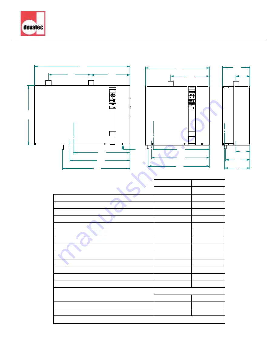
Dimensions
1
1
1
1
1
1
1
1
1
1
1
1
1
1
1
1
1
A
C
D
E
F
G
I
H
B
Face
Côté
H
F
A
D
N
M
N
O
L
Face
RTH-V2 5 to 50
RTH-V2 60 to 100
mm
mm
A Width
805
1200
B Height
750
750
C Depth
345
345
D Steam outlet 1
485
488
E Steam outlet - Side v iew
176
176
F Tank draining - Front view
730
759
G Tank draining - Side v iew
175
53
H Entrée d’eau - Face
710
692
I Water inlet - Side view
310
310
L Electrical wire outlet diameter
40 - 2x16
40 - 2x16
M Steam outlet 2
-
538
N Overf low draining - Front v iew
772
847
O Ov erflow draining - Side view
304
310
kg
kg
Weight in operation
75
140
Gross weight (packed)
45
70
RAL7035 powder coated metal case
Front
Front
Side