


4.12.20
Instruction manual ROTARNOCK 100 V. 3.6
29
Deutschmann Automation GmbH & Co. KG
Configurations ROTARNOCK 100
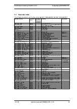
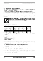
5.10.1 Logic functions and explanation of the used symbols
The following logic functions are available for selection:
„Not“ = the corresponding symbol in WINLOC32 is: „/“.
The following applies in the condition as delivered:
•
Ax = Nx
•
Mx = Nx
5.10.2 Priorities of the logic operations
Execution always takes place from left to right. There are no priorities.
In field 'TOFF', it is possible to enter a time from 0 to 255 ms for outputs 1 to 8 and the edge for
triggering can be defined, i. e. the output is switched off only after the entered time. The time
starts with the selected edge and is restarted (re-triggered) with each trigger condition.
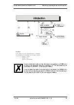
5.10.3 Operation mode of the shift register
The parameters of the shift register “data, pulse and reset“ are firmly assigned to the upper mark-
ers.
Here the following assignment applies:
M16 =
Shift register - Reset, if 1
M15 =
Shift register - Data input
M14 =
Shift register - Pulse (leading edge)
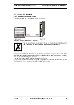
5.10.3.1
Example for the use of a shift register
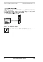
Referring to bottle manufacturing the finished product has to be analyzed for various criterions.
Therefore the bottles are handed over to a rotary table. For the examination they are placed in a
mechanically fixed position, in order to be driven past the different inspection equipment. The ini-
tialization of the test equipment is carried out through the standard outputs of the cam switch
unit.
Since it can always happen that no bottle is available when it comes to the supply of the part
under test, for instance due to a tailback on the feed belt or when a batch is coming to an end,
this would result in an error message of the camera. A possibility to avoid this is to use the shift
register integrated in the cam control.would be, to place an approximating pick-up at any test
position and to report the existence of a bottle to the test equipment. In order to realize that pos-
sibility, one single approximating pick-up at the intake to the rotary table is required. The informa-
Function
Symbol represented in the display of a connected TERM 24
UND
AND
UND_NICHT
AND_NOT
ODER
OR
ODER_NICHT
OR_NOT
Switch-off delay (time)
for outputs 1-8 only
TOFF
= 000
Output inverted
a
Marker inverted
m
Marker
M
Cam track (internal output)
N
Output
A
Shift register
S
Summary of Contents for ROTARNOCK 100
Page 2: ...Manual Art No V3408E...
Page 4: ...Deutschmann Automation GmbH Co KG 4 Instruction manual ROTARNOCK 100 V 3 6 4 12 20...
Page 57: ......
Page 58: ......


