


Pin assignment ROTARNOCK
Deutschmann Automation GmbH & Co. KG
20
Instruction manual ROTARNOCK 100 V. 3.6
4.12.20
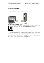
4.8 Signal description ROTARNOCK
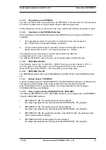
4.9 Program selection (through TERM)
In total the device supports 64 programs. Please take a look at the manual for the corresponding
terminal to learn how the program change-over is made.
The external program change-over of the programs 0 - 15 is another possibility (see also chapter
4.10 ’External program selection’).
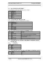
4.10 External program selection
For external program selection, the new program must be applied in the form of a binary code
(see chapter "Coding device and program numbers") at the connector strip and
then
a leading
edge must be generated at pin "ProgStart", whereby the High level (24V) must be held for at
least 200 ms.
The following steps are required if, for example, program 7 (binary 0111) is to be activated:
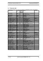
Function
Significance
Stan-
dard
PB
PB
IP65
PN
Output 1 ...
Output 8
Output block 1
Each output 24V / 0.3A plus-switching (PNP), short-circuit-
proof
Total current of the output block maximum 1 A
X
X
X
X
Output 9 ...
Output 16
Output block 2
Each output 24V / 0.3A plus-switching (PNP), short-circuit-
proof
Total current of the output block maximum 1 A
X
X
-
-
Output 9-12
Output block 2
Each output 24V / 0.3A plus-switching (PNP), short-circuit-
proof
Total current of the output block maximum 1 A
-
-
X
X
,
DICNET-
Data line for networking via the DEUTSCHMANN-bus system
DICNET (see chapter "DICNET®").
X
-
-
-
Rx
Receive signal RS232
X
X
X
X
Tx
Transmission signal RS232
X
X
X
X
24 V DC
Supply voltage 24 Volt DC
X
X
X
X
GND
Ground potential of the cam control
X
X
X
X
R+, R-
Terminating resistor connections for DICNET. Required, if
LOCON 32 is operated as first or last device in DICNET (see
X
-
-
-
ProgNo 1 ...
ProgNo 8
in case of external program selection the program number is
set at these pins. The coding takes place in a binary way
referring to the chapter "Coding device numbers".
X
X
-
-
ProgStart
If this pin is connected with 24V, the program number is taken
over at the pins ProgNo1 to ProgNo64 (see above).
X
X
-
-
nc
Not connected
Shield
A
Inverted input/output signal
-
X
X
-
B
Not-inverted input/output signal
-
X
X
-
P5
5V supply voltage
-
X
X
-
M5
Data reference potential
-
X
X
-
Incremental
output
Two output to complement an A/B-signal
-
X
-
Ext. PB-ID
selection
An external PB-ID selection from ID 1-15 can be performed
at the pins 9-12 through applying 24V.
-
X
-
RD -
Receive Data -
-
-
-
X
RD +
Receive Data +
-
-
-
X
TD -
Transmission Data -
-
-
-
X
TD +
Transmission Data +
-
-
-
X
Summary of Contents for ROTARNOCK 100
Page 2: ...Manual Art No V3408E...
Page 4: ...Deutschmann Automation GmbH Co KG 4 Instruction manual ROTARNOCK 100 V 3 6 4 12 20...
Page 57: ......
Page 58: ......