background image

65

Desert Aire - CM3500 Manual


 established. In this state the unit will stop and not restart until the alarm conditionis reset manually.  


The red ALARM LED on the display will stay lit until the alarm is reset.


3.1.21 Fixed Speed Compressor Phase Monitor


This is an Automatic Reset alarm. The FS Phase Monitor Alarm is activated when an Aura Q-Pump  


Inverter Plus unit requires a fixed speed compressor and the phase monitor detects that the fixed   


speed compressor will run backwards. In this state the unit will continue to run, but not allow the fixed  


speed compressor to run. The red ALARM LED on the display will stay lit until the alarm is reset.

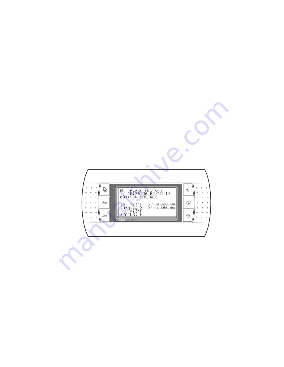
3.2.   Alarm History Screen (Figure 72)


The Alarm History Screen is accessible from the Alarm Screen by pressing the 

ALARM

 key. 


This screen lists a history of alarm conditions by time and date which have existed on the IAQ 


system. The most recent alarm will be displayed as 001 along with the Intake Air Temperature, 


Intake Air Relative Humidity, Supply Air Temperature, Suction Pressure, Discharge Pressure 


and the Status of the unit when the alarm occurred. On units with dual refrigerant circuits, the 


suction and discharge pressures of circuit B will also be shown when the alarm occurred. The 


Status number shown corresponds as follows: 0-Zone Satisfied/Off, 1-Heating, 2-Cooling, 


3-Dehumidifying, 4-Dehum/Heat, 5-Dehum/Cool and 6-Low Suction Pressure.


Figure 72


To access the history of alarms, press the 

DOWN

 key. The last 100 alarm conditions are saved


in this history with the 101st being overwritten.


Summary of Contents for CM3500 Series

Page 1: ...program capabilities Standard controller with interface mounted in unit Optional hand held user interface available Multiple communication interface options LonWorks BACnet Ethernet BACnet MS TP Modbus Precise temperature and humidity control CO2 monitoring and control ...

Page 2: ...2 ...

Page 3: ...r documentation provided 2 The Start Up Report must be completed and returned to Desert Aire Service for evaluation If no deficiencies are identified a Warranty Validation Letter will be issued that provides all warranty dates and coverage If installation or start up deficiencies are present these must be corrected and communicated to Desert Aire in order to activate warranty 3 This warranty shall...

Page 4: ...ersonal injury so the above limitations may not apply to you for certain damages This warranty gives you specific legal rights and you may also have other rights which vary from state to state No person or representative is authorized to make any warranty or assume any liability not strictly in accordance with the aforementioned Inquiries regarding warranty matters should be addressed to Desert Ai...

Page 5: ...5 Desert Aire CM3500 Manual Product Warning for the State of California ...

Page 6: ...6 Desert Aire CM3500 Manual ...

Page 7: ...ion 17 2 1 Menu Overview and General Instructions 17 2 2 Main Menu 18 2 3 Status Menu 19 2 3 1 Modes Time 19 2 3 2 I O Status 20 2 3 2 1 Digital Inputs 20 2 3 2 2 Analog Inputs 22 2 3 2 3 Digital Outputs 24 2 3 2 4 Analog Outputs 25 2 3 2 5 Room Sensor Data 26 2 3 2 6 Expansion I O 27 2 3 3 Starts Run Times 28 2 3 4 EXV EMV Status 28 2 4 Setpoint Menu 30 2 4 1 Blower Unit Setup 30 2 4 2 Damper Set...

Page 8: ...rol Settings 53 2 6 2 6 Enthalpy Wheel Settings 54 2 6 2 7 Condenser Settings 55 2 6 3 Sensor Offsets 56 2 6 4 Pressure SAT Alarms 58 2 6 5 Glycol Ratio 58 2 7 Unit Revision 59 3 Alarms 61 3 1 Alarm Menu 61 3 1 1 Alarm Screen 61 3 1 2 Low Suction Pressure 61 3 1 3 Motor Fault 62 3 1 4 High Discharge Pressure Circuit A or Circuit B 62 3 1 5 Multiple Low Suction Pressure Alarms Circuit A or Circuit ...

Page 9: ...rogrammable Controller 67 4 2 Remote Display Terminal 67 4 3 Remote Room Sensor 67 4 3 1 Remote Room Sensor Configuration 67 4 4 Suction Pressure Transducer 69 4 5 Discharge Pressure Transducer 69 4 6 Differential Air Pressure Transducer 69 4 7 CO2 Sensor 69 4 8 Supply Air Temperature Sensor 70 4 9 Intake Air Temperature and Relative Humidity Sensor 70 4 10 Air Flow Switch 70 5 Appendix 71 5 1 Rem...

Page 10: ...10 Desert Aire CM3500 Manual ...

Page 11: ... temperature sensor for the supply air If the unit was purchased with the zone reset option it also has one or multiple remote room sensors Additionally if the unit was purchased with the CO2 option it has an indoor and outdoor CO2 sensor 1 2 1 Duct Mount Sensor A duct mount sensor is normally used in applications where continuous blower operation is desired A duct mount sensor helps ensure consis...

Page 12: ...al length of the network must not exceed 1 500 feet The capacitance between the wires must not exceed 90 pF M See your wiring schematic for connection details CAUTION Undersized wiring will cause inaccurate sensor readings Do not run sensor wiring adjacent to OR in the same conduit as wires carrying more than 24 VAC These remote devices require a separate 24Vac 50 60HZ 1 5VA power connection Provi...

Page 13: ...trol or interlock with the room heating system This prevents wide fluctuations in room air temperature It also prevents the heater from trying to heat the room while the dehumidifier is running in the cooling mode 1 3 1 Auxiliary Heating Dry Contact Closure The standard Desert Aire CM3500 Controller provides a dry contact closure to operate the auxiliary space heater The contact closes to energize...

Page 14: ...ocations of the RDT up to 150 feet use a standard 24 AWG 6 conductor phone cable For locations of the sensor up to 1 500 feet use 22 AWG 3 twisted pair cable Pull the connector through the hole in the back of the mounting bracket Attach the bracket to the wall After plugging the cord into the back of the RDT feed any extra wiring back into the hole of the mounting bracket and gently snap the RDT i...

Page 15: ... RDT remains functional for safe and efficient unit operation If you think the RDT is not functioning correctly refer to the table below Problem Solution No LEDS lit on the remote terminal No power is getting to the remote terminal Check field wiring between remote terminal and controller Remote terminal shows NO LINK The display address has been altered Press the UP ENTER and DOWN keys together f...

Page 16: ...16 Desert Aire CM3500 Manual ...

Page 17: ...emote terminal top to bottom are the ALARM key shown as an alarm bell PROGRAM key abbreviated Prg and the ESCAPE key abbreviated Esc The keys on the right hand side of the remote terminal top to bottom are the UP key shown as an up arrow the ENTER key shown as a left arrow and the DOWN key shown as a down arrow The IDT also has a display screen and 6 keys The keys on the left hand side of the inte...

Page 18: ...values will require that the ENTER key be pressed to accept the value An ON or OFF selection will be altered as soon as the UP or DOWN keys are pressed To view the alarms from any menu simply press the ALARM key Press the UP and DOWN keys to display any active alarm When an alarm is triggered the red LED behind the ALARM key will light This LED will remain on until the alarm is acknowledged Alarm ...

Page 19: ...e blank or show the status of the Suction Valve for Aura Q Pump Inverter Plus units The damper state and the state of the damper end switch is shown on the next line The blower state and the state of the system switch is shown on the next line The compressor state and the occupied state either Occupied or Un Occupied is shown on the next line The Unit Status is shown on the next line and will show...

Page 20: ...from the STATUS MENU displays the Digital Inputs Analog Inputs Digital Outputs and Analog Outputs Room Sensor Data and Expansion I O will also be shown on this screen if these options were purchased with the IAQ system To return to the STATUS MENU press the Esc key Figure 8 2 3 2 1 Digital Inputs Figures 9 11 The Digital Input screens will show the state of the contacts wired into the controller T...

Page 21: ...sing the UP or DOWN keys from the first Digital Input screen will cycle through all applicable screens To return to the I O STATUS screen press the Esc key Figure 9 Figure 10 shows the following inputs Condensate Level Switch OK if the level is acceptable and Flt if a fault from a high condensate level switch is present Water Flow Switch On if the water flow is acceptable and Off when the water fl...

Page 22: ...gure 12 is shown as an example of what these screens looks like Refer to your schematic diagram for the specific devices provided Please note that sensors can be wired into ports J2 J3 J6 and J29 of the controller as well as into the EVD evolution valve driver and expansion I O devices The calculated values of superheat and sub cooling are also included in this series of screens Devices shown in t...

Page 23: ...P or DOWN keys from the first Analog Input Screen will cycle through all applicable screens Refer to your wiring schematic for the exact sensor wiring details of your dehumidifier To return to the I O STATUS screen press the Esc key Figure 12 Pressing the UP or DOWN keys will display the second Analog Inputs Screen Figure 13 if applicable If your unit comes standard with dual refrigerant circuits ...

Page 24: ...e devices can be wired into ports J12 J13 J14 J15 J16 J17 and J18 of the controller as well as into the expansion I O devices Devices shown in the Digital Output screens vary depending upon the type of dehumidifier provided They can include Compressor Contactors Solenoid Valves Heat Enable Dry Contacts Water Pump Alarm Dry Contact Damper Actuator or Fan Contactors Pressing the UP or DOWN keys from...

Page 25: ...or Off as required To return to the I O STATUS screen press the Esc key Figure 15 Figure 16 shows the following outputs Damper Actuator On or Off as required Supply Blower On or Off as required Exhaust Blower On or Off as required To return to the I O STATUS screen press the Esc key Figure 16 2 3 2 4 Analog Outputs Figure 17 The Analog Output screens will show the state of the devices wired Desert...

Page 26: ...ternal wheel module and set for Recirculation will also show the position of the O A and R A modulating damper actuators The Intake Air Dewpoint is also shown on this screen as this is a calculated output function Pressing the UP or DOWN keys from the first Analog Output screen will cycle through all applicable screens To return to the I O STATUS screen press the Esc key Figure 17 2 3 2 5 Room Sen...

Page 27: ...damper actuators of Aura units These screens are provided for troubleshooting of the control system Figure 19 is shown as an example of what these screens looks like Refer to your schematic diagram for the specific devices provided Devices shown in the Expansion I O screens vary depending upon the type of dehumidifier provided They can include sensing of the CO2 sensor enthalpy wheel differential ...

Page 28: ...Selecting the EXV EMV Status will display the status of the Electronic Expansion Valve EXV for the evaporator in circuit A The current superheat and suction temperature are shown The current suction pressure is shown at the bottom with the saturated suction temperature below the pressure The valve position is shown in steps and in percentage The status is also shown on the bottom left This is stri...

Page 29: ...alve position is shown in steps and in percentage The status is also shown on the bottom left This is strictly a display screen and is provided for troubleshooting of the unit To return to the STATUS MENU press the Esc key Figure 22 Pressing the DOWN key again will display the Electronic Motorized Valve EMV status for the two valves controlling the reheat condenser The valve position and status fo...

Page 30: ... DOWN keys and press the ENTER key to select To return to the MAIN MENU press the Esc key Figure 24 2 4 1 Blower Unit Setup Figure 25 Selecting the Blower Unit Setup enables adjustments to the operation of the damper and the operation of Output 8 The blower operation can be set for FIELD DAMPER RECIRCULATION or CONTINUOUS Set the blower operation for FIELD DAMPER when the intake air is supplied di...

Page 31: ...e Select the appropriate item with the UP and DOWN keys and press the ENTER key to select To return to the MAIN MENU press the Esc key Figure 25 2 4 2 Damper Setup Figure 26 Setting the blower operation for continuous or recirculation will allow the damper setup screen to be viewable Figure 26 This screen allows the positions of the outdoor air and recirculation air to be set in the Occupied and U...

Page 32: ...4 Zone Reset Setpoints Figure 28 In the Zone Reset mode of operation the Supply Air Temperature Setpoint is calculated based upon the actual zone air temperature and the zone air temperature set point and will fall between the High and Low Limit Set Points This mode requires the remote room sensor be installed in the conditioned space See section 2 4 4 1 for operation As the zone air temperature i...

Page 33: ...Locked mode none of the zone sensors allow this set point to be modified Also in the Zone Reset mode the Home Screen will display the actual zone air temperature instead of the supply air temperature To return to the SETPOINT MENU press the Esc key Figure 28 2 4 4 1 Operation of the Remote Room Sensor Figure 29 The remote room sensor supplied with the Zone Reset option will also allow modification...

Page 34: ...ed The bottom left button on the remote room sensor flips the large temperature and small humidity display to the large humidity and small temperature display for a few seconds This allows the humidity to be displayed in a larger font The remaining buttons on the left of the remote room sensor are disabled for this application Pressing them will display an icon of a lock The remote room sensor wil...

Page 35: ...he second highest SAT Set Point The second highest SAT Set Point cannot be set higher than the highest SAT Set Point and lower than the second lowest SAT Set Point The second lowest SAT Set Point cannot be set higher than the second highest SAT Set Point and lower than the lowest SAT Set Point The lowest SAT Set Point cannot be set higher than the second lowest SAT Set Point To modify the set poin...

Page 36: ...re 31 2 5 Occupancy Menu Figure 32 Select the OCCUPANCY MENU from the MAIN MENU allows access to the 10 occupancy schedules in the controller as well as adjusting the current date and time From this menu it is possible to access and adjust the Schedule Options Temporary Holidays Annual Holidays Temporary Occupancy and the Time settings To return to the MAIN MENU press the Esc key Figure 32 Desert ...

Page 37: ...the occupancy timing to be set for the selected day of the week DOW Select the schedule to modify the start time and stop time This is the time span that the unit will be in the occupied mode All times are set in the 24 hour format As the DOW is selected the UP and DOWN keys allow for Monday Tuesday Wednesday Thursday Friday Saturday Sunday and any holiday to be occupied during that time Up to 10 ...

Page 38: ...te and the End Date for that holiday To return to the OCCUPANCY MENU press the Esc key Figure 35 2 5 3 Annual Holidays Figure 36 The Annual Holiday settings are for holidays with dates that remain constant year to year such as New Years Day and the 4th of July Up to 10 different annual holidays can be set from this screen Select the number to assign to the Annual Holiday and then select the Start ...

Page 39: ...he schedule and allow the unit to be temporarily occupied The screen will now show Override On To clear this occupied override set the hours and minutes to zero and press the Prg key The screen will now show Override Off To return to the OCCUPANCY MENU press the Esc key Figure 37 2 5 5 Set Time Figure 38 This screen sets the time date and day of week To modify these settings press the ENTER key un...

Page 40: ... 40 will now be shown This menu gives access to the Unit Setup Parameter Settings Sensor Offsets and Pressure SAT Alarms If the unit is a heat pump the Glycol Ratio screen will also be available The user remains logged in for 10 minutes after the password is entered During this time the Login screen reads Still Logged In Press PRG to Enter During these 10 minutes the service menu may be re entered...

Page 41: ...t Set Point and Deadband can be modified on this screen This factory set point is preset before the controller is shipped and should only be modified by a trained technician The range of the Intake Air Dewpoint set point is 0 0º to 99 9º F with a default of 60 0º F The range of the Deadband is 0 0º to 9 9º F with a default of 3 0º F The Actual Intake Air Dewpoint is shown for reference To modify s...

Page 42: ...Air Set Point is 72 0ºF using the deadbands and switch differential shown the cooling mode will be required when the intake air temperature is above 72 0ºF plus the 2 0 ºF deadband or any temperature above 74 0ºF The cooling mode will cease at 1 0ºF below 74 0ºF or any intake air temperature below 73 0ºF The heating mode will be required when the intake air temperature is below 72 0ºF minus the 2 ...

Page 43: ... the Timer Settings screens vary depending upon the type of dehumidifier provided They can include the timing for the multi stage heating controller Up to 3 stages of heat can be set at the factory This control will employ a vernier sequence which will allow the first stage to be variable from the auxiliary heat analog output The second or third stage will be cycled on sequentially after the analo...

Page 44: ...will not set the low air flow alarm during this initial start After this time a low air flow condition will need to be present for the Air Flow Delay time to set the alarm The Damper On Fan Delay will delay the start of the fan until the damper has been energized for the delay time After this time the fan will start if the damper end switch is closed Aura Q Pump Inverter Plus models will also incl...

Page 45: ...nformational purposes only Figure 46 Pressing the DOWN key will display the screen on Figure 47 This screen is used to modify the minimum air flow set point The minimum air flow set point is used to set the low air flow alarm for Aura units The fan DP has to be lower than 80 of the set point to set the alarm The fan DP is shown on this screen for informational purposes only The filtering time is u...

Page 46: ...he Fan DP is also set here The actual fan DP and Loop Output are displayed here to aid in the tuning of the PID loop To modify these set points press the ENTER key and use the arrow keys until the desired setting is shown Pressing the ENTER key will now change the set point Figure 48 Pressing the DOWN key will display the Manual Blower Setup screen shown on Figure 49 The supply air blower can be s...

Page 47: ...ssor is running at minimum speed The Dehum PID Settings shown in Figure 50 allows the PID loop for dehumidification mode to be modified The PID setting of the Gain or Proportional Band Reset or Integral and the Rate or Derivative can be modified here The range of the Gain is 0 to 32767 The range of the Reset is 0 to 32767 The range of the Rate is 0 to 32767 The Off Evaporator temperature is shown ...

Page 48: ... in this mode The Loop Cmd is also displayed here to aid in the tuning of the PID loop To modify these set points press the ENTER key and use the arrow keys until the desired setting is shown Pressing the ENTER key will now change the set point Figure 51 Pressing the DOWN key will display the Htpmp PID screen shown on Figure 52 This screen allows the PID loop for heating mode to be modified The PI...

Page 49: ...isabled The PID loop settings for the precision cooling can also be modified here The PID setting of the Gain or Proportional Band Reset or Integral and the Rate or Derivative can be modified here The range of the Gain is 0 to 32767 The range of the Reset is 0 to 32767 The range of the Rate is 0 to 32767 The supply air temperature is shown here as well as the set point used in this mode The Loop C...

Page 50: ...t used in this mode The maximum limit of the unloader valve can also be set here from 0 0 to 100 0 The Loop Cmd is also displayed here to aid in the tuning of the PID loop To modify these set points press the ENTER key and use the arrow keys until the desired setting is shown Pressing the ENTER key will now change the set point Figure 54 2 6 2 Parameter Settings Figure 55 Selecting the Parameter S...

Page 51: ...ng of the PID loop To modify these set points press the ENTER key and use the arrow keys until the desired setting is shown Press the ENTER key to accept the set point value To return to the Parameter Settings press the Esc key Figure 56 2 6 2 2 Auxiliary Heat Control Settings Figure 57 This screen allows the Auxiliary Heat PID Gain or Proportional Band Reset or Integral and the Rate or Derivative...

Page 52: ...llows the Extended Heat Control PID Gain or Proportional Band Reset or Integral and the Rate or Derivative to be modified for loop tuning The range of the Gain is 0 0º F to 999 9º F The range of the Reset is 0 to 999 The range of the Rate is 0 to 999 The Supply Air Temperature Set Point and actual loop output are displayed here to aid in the tuning of the PID loop To modify these set points press ...

Page 53: ...gs press the Esc key Figure 59 2 6 2 5 Zone Control Settings Figure 60 This screen will only be shown if the Zone Reset option is selected in the unit setup This screen allows the Zone Reset PID Gain or Proportional Band Reset or Integral and Rate or Derivative to be modified for loop tuning The range of the Gain is 0 0º F to 99 9º F The range of the Reset is 0 to 999 The range of the Rate is 0 to...

Page 54: ...shown The range of the Gain is 0 0 to 99 9 The range of the Reset is 0 to 999 The range for the Set Point is 0 0 to 99 9 To modify these set points press the ENTER key until the desired set point is selected and use the arrow keys until the desired setting is shown Press the ENTER key to accept the set point value To return to the Parameter Settings press the Esc key Figure 61 The screen shown in ...

Page 55: ...n to the Parameter Settings press the Esc key Figure 62 2 6 2 7 Condenser Settings Figures 63 64 This screen will only be shown if the Condenser Control option is selected in the Factory Configuration On a single circuit system the discharge pressure controls the cycling of the condenser fans based upon the set points listed On a dual circuit system the highest discharge pressure controls the cycl...

Page 56: ...2 6 3 Sensor Offsets Figures 65 66 These screens allow for the control values of the analog input points to be adjusted if calibration shows these devices to be inaccurate More than one Sensor Offset screen may be provided depending upon the optional equipment included with your dehumidifier Pressing the UP or DOWN keys from the first Sensor Offset Screen Figure 65 will cycle through all applicabl...

Page 57: ...ion I O boards to be adjusted if calibration shows these devices to be inaccurate This screen will only be shown if an expansion I O board is wired into the controller The range for the air pressure and CO2 sensors is 99 to 99 The range for the temperatures and humidity sensors is 99 9 to 99 9 Care must be used when applying an offset to an analog value as erratic operation can result To modify th...

Page 58: ... F default The range of the SAT delay varies from 0 minutes to 30 minutes with a 10 minutes default To modify these set points press the ENTER key and use the UP and DOWN arrow keys until the desired setting is shown Press the ENTER key to accept the set point value To return to the SERVICE MENU press the Esc key Figure 67 2 6 5 Glycol Ratio Figure 68 This screen will only be shown if the unit is ...

Page 59: ... software This information should be passed to Desert Aire in the event a service call is necessary When an order number is shown on this screen the controller program may have been modified from the standards described in this manual See the order documentation for further details To return to the MAIN MENU press the Esc key Figure 69 Desert Aire CM3500 Manual ...

Page 60: ...60 Desert Aire CM3500 Manual ...

Page 61: ...be accessed anytime by pressing the ALARM key The main alarm screen includes the instructions for viewing and resetting the alarms as well as a means to access the alarm history page Pressing the ENTER key while viewing this alarm screen or the active alarm will reset any alarm that has returned to its safe state Any active alarm can be viewed by pressing the DOWN key from this page If no active a...

Page 62: ...nual Reset Alarm after a number of attempts If the low suction pressure cycle occurs 3 adjustable times in a 1 adjustable hour time period then an alarm will be indicated and recorded in the alarm history as a multiple suction pressure alarm This alarm will be reset by the controller after a 2 adjustable hour time delay This controller reset will be tried 3 adjustable times in a 36 adjustable hour...

Page 63: ...M LED on the display will stay lit until the alarm is reset 3 1 10 Low Voltage Monitor This is an Automatic Reset Alarm The optional Low Voltage Monitor is required to activate this alarm The Low Voltage Monitor Alarm is activated when Low Voltage Monitor senses a below normal voltage in the unit low enough to damage the equipment The unit will stop and the Low Voltage Alarm will be activated The ...

Page 64: ...devices trip The unit will continueto run the red ALARM LED on the display will stay lit until the alarm is reset 3 1 17 High Discharge Temperature Alarm This is a Manual Reset alarm The High Discharge Temperature Alarm is activated when the compressor temperature rises to an unacceptable level In this state the unit will stop and not restart until the alarm condition is reset manually The red ALA...

Page 65: ...en Figure 72 The Alarm History Screen is accessible from the Alarm Screen by pressing the ALARM key This screen lists a history of alarm conditions by time and date which have existed on the IAQ system The most recent alarm will be displayed as 001 along with the Intake Air Temperature Intake Air Relative Humidity Supply Air Temperature Suction Pressure Discharge Pressure and the Status of the uni...

Page 66: ...66 Desert Aire CM3500 Manual ...

Page 67: ...l be address 5 The addresses are set in the PARAMETER MENU of the Remote Room Sensor Holding both the UP and DOWN buttons together for 4 seconds will display the PARAMETER MENU While continuing to hold the UP button press the button on the lower left of the Remote Room Sensor to enter the menu The settable parameters can now be seen using the UP or DOWN buttons To modify a parameter press the lowe...

Page 68: ...er the room sensor network connection has failed An alarm condition is displayed as ALr and will flash between the room temperature and ALr A bell icon will also blink on the display The occupancy of the unit will be displayed as a house icon to the left of the room temperature If the house icon is empty the dehumidifier is in the un occupied mode If a human figure is in the house the dehumidifier...

Page 69: ...e body is brass with a SAE female refrigerant connection This transducer must be supplied with 4 5 to 5 5 VDC power A display reading of 0 0 psig for the transducer indicates the device is disconnected or defective For this device to function 5 0 VDC must be present from the black to the green wires on the transducer To verify the output of the transducer measure the DC voltage should read between...

Page 70: ...d Relative Humidity Sensor is internally mounted in the air stream of the unit behind the air filter The Temperature Sensor is a resistive NTC Bulb type device The failure mode of this device will display a reading of 623 3º F if the sensor is open and display a reading of 687 3º F if the sensor is shorted A reading of 0 0 humidity indicates a failure of the RH sensor The Desert Aire replacement p...

Page 71: ...et Ethernet Setting IP Address Via the PGD Hold the alarm button and the enter button for 5 seconds The following screen will appear Figure 74 Select OTHER INFORMATION and the following screen will appear Figure 75 Select PCOWEB NET CONFIG and the following screen will appear ...

Page 72: ... the IP address DHCP should be set to off Set IP address as instructed by Controls contractor Figure 77 After the IP address has been set the screen will switch to the following page Set the Netmask as well as the Gateway addresses The Netmask and the Gateway addresses will be provided by the Controls contractor ...

Page 73: ...DNS addresses are required they would be entered here This is not common The Controls contractor would also need to provide these addresses Figure 79 Next you will see the BACnet ID and BACnet Type screen This is also very rarely used however if necessary needs to be provided by the Control contractor Set appropriately ...

Page 74: ...ntroller will then prompt you to save the changes Select YES and hit enter Figure 81 The controller will then verify that the update was complete and ask you to reboot the pCOnet Cycle power to the dehumidifier Figure 82 Addressing is now complete ...

Page 75: ... TP Addressing Via the PGD Hold the alarm button and the enter button for 5 seconds The following screen will appear Figure 83 Select OTHER INFORMATION and the following screen will appear Figure 84 Select PCOWEB NET CONFIG and the following screen will appear ...

Page 76: ... Rate Set as instructed by Controls contractor Figure 86 After the baud rate has been set the screen will switch to the following page Set the BACnet MAC address as well as the Max Master and Max Info Frames The MAC address will be provided by the Controls contractor Default values for the Max Master is 127 and Max Frames is 20 ...

Page 77: ...l Figure 87 The controller will then prompt you to save the changes Select YES and hit enter Figure 88 The controller will then verify that the update was complete and ask you to reboot the pCOnet Cycle power to the dehumidifier ...

Page 78: ...78 Desert Aire CM3500 Manual Figure 89 Addressing is now complete ...

Page 79: ...79 Desert Aire CM3500 Manual ...

Page 80: ...MIZING SOLUTIONS THROUGH SUPERIOR DEHUMIDIFICATION TECHNOLOGY N120 W18485 Freistadt Road Germantown WI 53022 E mail info desert aire com Ph 262 946 7400 Fax 262 946 7401 Website www desert aire com 327 2018 12 ...

Reviews: