3. Maintenance and troubleshooting
MERMAID E1100-I
STD00
Page 25 of 54
Separate the head (fig.15, position 1) and the liner manifold (fig.16, position 2) from the pump
crankcase (fig.16, position 3)
Remove the screws M 8x100 that fasten the liners to the head as shown in fig. 17 and proceed as
indicated in fig. 18.
If the valve seats are blocked on the head due to the formation of limestone or oxide, they must be
freed by inserting the opposite tool in the suction hole and operating as in fig. 20.
Extr
act the valve seat (fig. 21, position 1)
;
check components for wear and replace them if necessary.
At every valve inspection, always replace all the sealing rings and the OR rings between the liner
and the head, between the head and the liner manifold in the area of the recirculation hole.
Before reassembly, clean and dry off the components and all their seats inside the head.
Summary of Contents for MERMAID E1100-I
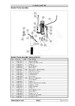
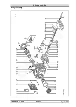
Page 38: ...4 Spare parts list MERMAID E1100 I STD00 Page 37 of 54 Pump assembly ...
Page 46: ...4 Spare parts list MERMAID E1100 I STD00 Page 45 of 54 ...
Page 47: ...4 Spare parts list MERMAID E1100 I STD00 Page 46 of 54 ...
Page 53: ...5 Wiring Diagram MERMAID E1100 I STD00 Page 52 of 54 5 Wiring Diagram ...


