background image


- 194 - 

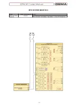
APPLICATION DIAGRAM NO.9 


Function

Function Activation Address

Settings

CB Trip Circuit 
Supervision

MENU » Auto. Control Settings » 

CB Supervision Settings

Input

MENU » Automatic Control Settings » Input Settings » 1-5.Input » Trip Circuit Superv.

Summary of Contents for CPM 311

Page 1: ......

Page 2: ...ting p 43 4 4 1 Example Setting and Calculation p 44 4 4 2 Dip switch Settings p 47 4 4 3 Example Dip switch Settings p 49 4 4 4 Warnings p 49 4 5 Commissioning p 50 4 6 Operating p 51 4 6 1 Normal Operation p 51 4 6 2 Fault Diagnosis and Maintenance p 51 4 6 3 Recommissioning p 51 4 7 Testing Maintenance Reparation p 52 5 Relay Menus Manual p 53 5 1 Introduction p 54 5 2 The Menu Tree p 55 5 3 Re...

Page 3: ...Settings Menu p 105 5 7 6 4 Input Settings Menu p 106 5 7 6 5 Blocking Logic Selectivity Settings Menu p 107 5 7 6 6 Circuit Breaker Failure Recognition Settings Menu p 110 5 7 6 7 Auxiliary Timer Settings Menu p 112 5 7 6 8 Delaying Logic Selectivity Settings Menu p 113 5 7 6 9 Auto recloser ARCL Settings Menu p 114 5 7 6 10 CB Supervision Settings Menu p 117 5 7 6 11 Programmable LEDs Settings M...

Page 4: ...ettings p 168 6 4 4 4 11 Programmable LED Settings p 169 6 4 4 4 12 Latch Settings p 170 6 4 4 4 13 Alarm Settings p 171 6 4 4 5 Communication Settings p 172 6 4 5 Buffer Menu p 173 6 4 6 Disturbance Waveform Records Menu p 179 7 Application Diagrams p 188 7 1 On the Use of Application Diagrams p 189 7 2 Sample Application p 189 7 3 Fundamental Cabling Diagram p 192 7 4 Application Diagram No 1 p ...

Page 5: ...DMT delay 1997 MVR Series The first draw out type electronic over undervoltage protection relay series in the country with DMT and IDMT delay 2000 IR1021 Double flashing annunciator relay with LEDs 2006 CPM Series The first draw out type DSP based digital overcurrent protection relay with digital communication and LCD display features 2011 CPM 311 The first digital relay with separate control and ...

Page 6: ... plastic electro mechanical and graphical components used in DEMA s products are designed prototyped and manufactured in the same facility by DEMA engineers and technicians 50 of DEMA s total revenue comes from international sales with an increasing proportion DEMA imported to over 10 countries all over the world in 2009 The innovative and leading policy of DEMA has been recognized and awarded by ...

Page 7: ...MVR 300 3 modules over undervoltage protection relay in draw out case MVR 400 4 modules over undervoltage protection relay in draw out case 3 Annunciating System Components IT1 6 6 windows optical annunciator K 101 A2 Multitone acoustic horn annunciator KR30 Horn Relay IR61K A2 6 windows optical annunciator with relay and horn outputs in draw out case IR101K A2 10 windows optical annunciator with ...

Page 8: ...e Tic A S Zumrutevler Mh Ataturk Cd Inanc Sk No 4 34852 Maltepe Istanbul Turkey Phone 90 216 352 77 34 90 216 352 77 35 Fax 90 216 442 17 95 E mail dema demarelay com WEB www demarelay com DEMA Role San ve Tic A S Plant at Istanbul Turkey ...

Page 9: ... 9 INTRODUCTION ...

Page 10: ...ted in internationally accredited laboratories to comply with IEC 60255 IEC 60529 IEC 60695 and IEC 60068 standards and have been introduced into service under the guarantee of ISO9001 2008 The general specifications of CPM 311 are listed below to create a common sense for the product Function ANSI Code CPM 311 Phase Overcurrent Protection Instantaneous 50 3 thresholds Phase Overcurrent Protection...

Page 11: ...lity for each protection function Cold load pickup function with high reliability CB triggering Blocking logic selectivity feature Delaying logic selectivity feature Circuit breaker failure supervision and alarming Circuit breaker supervision functions opening and closing time supervision charging spring supervision numerator ΣA and ΣA supervision for each pole trip circuit supervision Main menu t...

Page 12: ...nge between the main and control units and the other one is the protective earth conductor of the control unit No other cabling is required on the panel door CPM 311 Control Unit can be replaced during operation if needed During the replacement the main unit functions normally without having to interrupt the facility protection Once the replacement is completed restarting the relay will provide th...

Page 13: ...If the phase overcurrent protection I is activated this LED will run continuously red in case of phase overcurrent tripping o I If the phase short circuit protection I is activated this LED will run continuously red in case of phase short circuit tripping Earth Protection LEDs 4 earth protection LEDs are located on the front side of the CPM 311 Control Unit o Ie If the earth overcurrent protection...

Page 14: ...rovided along with the product is plugged into that terminal The cable enables the data exchange between the main and control units Ground Terminal The protective earthing connection of the control unit is achieved via this terminal Appropriate cable lugs are provided within the product box USB Port USB communication port is the connection point for PC communications via DigiConnect software Conne...

Page 15: ...e to ensure maximum operating reliability Auxiliary Supply Terminals The auxiliary supply conductors and the operating ground conductor are to be connected on these terminals The terminals are of plug receptacle type Output Terminals The trip watchdog and 2 programmable output conductors are to be connected on these terminals The terminals are of plug receptacle type Input Terminals The common sup...

Page 16: ...Faraday cage around the main circuits filtering any electromagnetic and electrical disturbances that may otherwise impact the healthy operation of the relay Just like any other electrical appliance solid grounding of the main unit is essential to provide maximum protection for the operators and the relay RJ45 Terminal One end of the RJ45 terminated communication cable provided along with the produ...

Page 17: ...rs are integrated into the internal unit this guarantees fast maintenance and replacement operations without having to carry out calibration procedures Fuse Holder The T1A fuse protecting the main unit circuits is mounted on this fuse holder The fuse ensures the protection of the circuits in case of any auxiliary supply faults and provides maximum service continuity The placement of the fuse holde...

Page 18: ...ent Protection ANSI 37 This function is used in applications where undercurrent monitoring is required e g tripping of a contactor controlling a water pump when the water source is exhausted The function requires a 52a normally open contact signal for reliable operation Setting zone is I 0 02 1 0 In Negative Sequence Overcurrent Protection ANSI 46 Unbalanced phase current conditions without earth ...

Page 19: ...gering of a programmed input Circuit Breaker Trip Circuit Supervision ANSI TCM The trip circuit of a circuit breaker comprises the trip coil the trip output of a relay and the cabling between them An open circuit on one of these components would prevent the correct operation of the CB when needed CPM series relays are capable of supervising the condition of the trip circuit continuously by one of ...

Page 20: ... 103 communication protocols at rates between 1 200 bauds and 38 400 bauds Measurement Functions CPM series relays feature the following measurement functions Frequency measurements The primary circuit power frequency once the secondary current exceeds 0 1 In Current measurements The momentary maximum RMS current values and fundamental harmonic value of the phases and the earth circuits Positive n...

Page 21: ...MT IEC Very Inverse IEC VI 13 5s 1 0 TMS 0 025 3 2 DMT 0 04 100s DMT IEC Extremely Inverse IEC EI 80s 2 0 TMS 0 025 3 2 DMT 0 04 100s DMT IEC Long Time Inverse IEC LTI 120s 1 0 TMS 0 025 3 2 DMT 0 04 100s DMT IEC Semiconductor Protection SA Semic 35 500s 6 0 TMS 0 025 3 2 DMT 0 04 100s DMT Special Curve SA Definite Inverse DI SB DI 2 96875s 2 3 1 96875s TMS 0 025 3 2 DMT 0 04 100s DMT Special Curv...

Page 22: ...bove while IEC constants for various curves are given on the below table t Trip delay s A A constant for the characteristic s I Momentary current A Is Set current threshold A α A constant for the characteristic B A constant for the characteristic s TMS Time Multiplier Setting Curve Type Trip Delay Formula Reset Delay Setting Zone IEC STI Short Time Inverse 𝒕 𝟎 𝟎𝟓 𝒔 𝑰 𝑰𝑺 𝟎 𝟎𝟒 𝟏 𝑻𝑴𝑺 𝒕𝑹𝒆𝒔𝒆𝒕 𝑫𝑴𝑻 𝟎 𝟎𝟒 ...

Page 23: ... 23 The image below shows the trip delay curves for all IEC characteristics with TMS 1 TMS can be set within the range of 0 025 3 2 for any protection function ...

Page 24: ...curves for its impossible to demonstrate all of the curves on a chart sample curves are given on the below chart to express an overview of the characteristic 𝑡 𝑇𝑒 loge 𝐼 𝑘 𝐼Θ 2 Θ𝑝 𝐼 𝑘 𝐼Θ 2 Θ𝑡𝑟𝑖𝑝 t Trip time delay minute Te Thermal Constant minute setting range 1 200 min in 1 min steps k Trip Threshold Translation Constant setting range 1 00 1 50 in 0 01 steps I RMS value of load current A Iθ Set c...

Page 25: ...is given above while ANSI IEEE constants for various curves are given on the below table t Trip delay s A A constant for the characteristic s I Momentary current A Is Set current threshold A α A constant for the characteristic B A constant for the characteristic s TMS Time Multiplier Setting Curve Type Trip Delay Formula Reset Delay Setting Zone ANSI IEEE MI Moderately Inverse 𝒕 𝟎 𝟎𝟓𝟏𝟓 𝒔 𝑰 𝑰𝑺 𝟎 𝟎𝟐...

Page 26: ... 26 The image below shows the trip delay curves for all ANSI IEEE characteristics with TMS 1 00 TMS can be set in the range 0 025 3 2 for any protection function ...

Page 27: ...ow table t Trip delay s A A constant for the characteristic s I Momentary current A Is Set current threshold A α A constant for the characteristic B A constant for the characteristic s TMS Time Multiplier Setting Curve Type Trip Delay Formula Reset Delay Setting Zone SA Semic Semiconductor Protection 𝒕 𝟑𝟓𝟓𝟎𝟎 𝒔 𝑰 𝑰𝑺 𝟔 𝟏 𝑻𝑴𝑺 𝑫𝑴𝑻 𝟎 𝟎𝟒 𝟏𝟎𝟎 𝒔 SB DI Definite Inverse 𝒕 𝟐 𝟗𝟔𝟖𝟕𝟓 𝒔 𝑰 𝑰𝑺 𝟐 𝟑 𝟏 𝟏 𝟗𝟔𝟖𝟕𝟓 𝒔 𝑻𝑴𝑺 ...

Page 28: ... 28 The image below shows the custom trip delay curves with TMS 1 00 TMS can be set in the range 0 025 3 2 for any protection function ...

Page 29: ...s used for obtaining constant trip and reset delays There are no parameters for the DMT characteristic other than the constant trip or reset delay Characteristic notation is as follows e g t DMT 0 25 s The image below shows the DMT characteristics for given current values ...

Page 30: ...1 protects The RIDMT parameters differ with the tripping curve they are based on The table CPM 311 Protection and Reset Curves Parameters on page 16 shows these parameters The sample image below shows the CO2 short time inverse trip characteristic and its RIDMT curve The formula given below explains the calculation method of the reset delay for CO2 RIDMT curve 𝒕 𝟔 𝟗 𝒔 𝟏 𝑰 𝑰𝑺 𝟐 𝑹𝑻𝑴𝑺 Sample IDMT for...

Page 31: ... 31 PACKING LABELING INFORMATION ...

Page 32: ...er Logo DEMA Product Name CPM 311 Ordering Code 1 11AB Product Description Digital Multifunction Overcurrent Relay 3Ph E Rated Frequency 50 Hz 60 Hz Unit Serial Number A1234567 Nominal Phase Current 1 5 A Nominal Earth Current 1 5 A Earth Protection Setting Range 0 02 5 Ien 0 1 40 Ien Auxiliary Supply Voltage 24 250 VDC 100 250 VAC The default settings for the Nominal Phase Current Nominal Earth C...

Page 33: ... 33 OPERATING MANUAL ...

Page 34: ...dımlar aşağıdaki şemada gösterilen şekildedir Her bir adım ile ilgili ayrıntılı açıklamalar ilerleyen sayfalardaki bölümlerde bulunabilir İşletme Kılavuzu nda cevabını bulamadığınız sorularınız öneri ve şikayetleriniz için lütfen teknik ekibimizle iletişim kurunuz Teknik Sorumlu Elek Müh Necati Özbey Tel 90 216 352 77 34 90 216 352 77 35 Fax 90 216 442 17 95 e mail necati demarelay com WEB www dem...

Page 35: ...kutusunun çizilmesi ve montaj hataları engellenmelidir o Sac panolarda kesim yüzeyine uygun anti pas malzeme uygulanarak paslanma önlenmelidir o Kesim yüzeyine standart miktarda boya uygulanarak korozyona karşı önlem alınmalıdır CPM 311 Kontrol Ünitesi montajı için pano kapağı kesim ölçüleri KONTROL ÜNİTESİNİN MONTAJI Kesim ve boyama işlemleri tamamlanmış pano kapağına kontrol ünitesinin montajı a...

Page 36: ...ikleri delinerek hazırlanmış taban sacı üzerine oturtulur 2 Montaj malzemeleri poşetinden çıkan civatalar kullanılarak ana ünite montaj sacına sabitlenir 3 Montaj malzemeleri poşetinden çıkan topraklama kablosu ucu kullanılarak ana ünite topraklama terminalinin kablajı yapılır 4 Bir ucu kontrol ünitesine bağlanmış olan Üniteler arası bağlantı kablosu nun diğer ucu ana ünitenin sağ yan yüzünde bulu...

Page 37: ...pply cabling is decided according to the following assumptions The input signals from external devices e g from the Buchholz relay of the power transformer are in DC polarity The output signals to external devices e g to the tripping coil of the circuit breaker are in DC polarity If the actual circuit design does not meet these assumptions common supply cabling should be arranged accordingly As sh...

Page 38: ...ış aletlerle soyulmamalıdır Tüm kablo uçları kablo ucu açma pensesi ile açılmalıdır o Çok damarlı kabloların dış izolasyonları bu amaç için dizayn edilmiş özel bıçaklar ile açılmalıdır Uygun olmayan aletlerle izolasyonun soyulması kısadevrelere veya sekonder koruma hatalarına neden olabilir o Klemens civataları 0 56 0 69 N m aralığındaki tork değerleri ile sıkılmalıdır bu amaçla tork ayarlı tornav...

Page 39: ...kte yolverme giriş ve çıkış trip blokaj kesici kutup hatası izleme timer gecikme selektivitesi tekrar kapama kesici denetimi LED kilitleme ve alarm ayarlarından gerekli olanların yapılması Sistem Ayarları s 97 Sistem Ayarları Menüsü nde saat tarih şebeke frekansı röle tanımı şifre sembolizasyon koruma grubu faz rotasyonu ekran aydınlatma ve dil seçimi ayarlarından gerekli olanların yapılması veya ...

Page 40: ...ılır 2 Kablajı tamamlanarak yardımcı beslemesi sağlanmış CPM 311 in iç ünitesi kutusundan çıkartılarak dışarı alınır Koruma akım trafosu sekonder nominal akımı 5 A olduğundan dip switch lerin fabrika çıkış ayarları olan ON ON ON ON ON konumunda olduğu kontrol edilir bkz s 47 daha sonra iç ünite kutuya sürülür ve kilitlenir 3 Koruma akım trafosu 60 5 A olarak seçildiğinden Akım Trafosu Ayar Menüsü ...

Page 41: ...𝑈𝑛 2500 𝑘𝑉 𝐴 3 34 5 𝑘𝑉 41 84 𝐴 Güç transformatörü nominal akımının akım trafosu primer nominal akımına oranı 𝐼rTR 41 84 𝐴 60 𝐴 0 70 𝐼𝑛 Termik korumanın 1 00 IrTR nin üzerinde çalışması düşünülerek aşağıdaki ayarlar yapılır I Faz Aşırı Akım Koruması nın Yapılması b Güç transformatörü aşırı akım koruma eşiği 1 3 IrTR olarak alınırsa aşırı akım eşiğinin akım trafosu primer nominal akımına oranı 𝐼 1 3...

Page 42: ...ası korumalarında 1 s lik kesici açtırma gecikmesi uygun olacaktır 𝐼𝑒 15 𝐴 60 𝐴 𝐼𝑒𝑛 0 25 𝐼𝑒𝑛 g Elde edilen değerlerle Ie Toprak Aşırı Akım 1 Eşik Koruması aşağıdaki şekilde ayarlanır Ie Toprak Kısadevre Koruması nın Yapılması h Güç trafosunu besleyen dağıtım fiderindeki toprak kısadevre eşik değerinin 50 A olduğu varsayılırsa bunun en az 10 altında bir toprak kısadevre eşiği belirlemek uygun olur ...

Page 43: ... sinyallerini üreten bileşenler olduklarından sekonder koruma sistemlerinde önemli yere sahiptirler Akım trafolarının seçim ve uygulamalarının yanlış yapılması sekonder koruma sistemlerinin performansını düşürür istenen korumanın yapılamamasına veya besleme sürekliliğinin sağlanamamasına yol açabilir Akım bilgisinin doğru şekilde izlenmesi ve işlenmesi için akım transformatör uygulamalarının sağlı...

Page 44: ... switch lerin üstten görünümü 3 Sistemde kullanılan akım trafolarının karakteristikleri ve koruma uygulaması için gerekli olan ayar sahası belirlenerek dip switch ayarları aşağıdaki tabloya göre yapılır Dip switch ayar tablosu NOT T1 tipi dip switch ayarı yapıldığında toprak koruma fonksiyonlarının ayar sahası 0 1 40 Ien T2 tipi dip switch ayarı yapıldığında toprak koruma fonksiyonlarının ayar sah...

Page 45: ...Ien olacaktır ve Ien 5 A dir Önceki sayfadaki tablodan görüleceği gibi dip switchlerden E1 no 1 ve E2 no 2 ON olarak ayarlanmıştır Röle menülerinden akım trafosu ayarları yapılarak işlem tamamlanır UYARILAR DEMA CPM Serisi Aşırı Akım Koruma Röleleri fabrikadan ON ON ON ON ON dip switch ayarları ile sevk edilir Bu fabrika ayarlarına göre akım trafolarının nominal sekonder akımları In 5 A dir ve faz...

Page 46: ...1 ölçüm menüleri kullanılarak faz rotasyonunun kontrolü gerekirse düzeltici işlemlerin yapılması Devreye Alma Primer devrenin enerjilendirilmesi Fonksiyon Testi CPM 311 fonksiyon test işlevi kullanılarak röle fonksiyonlarının ve kablajının kontrolü Kesici Kontrolü Kesici primer devre testleri ve gerekirse bakımının yapılması kumanda bobinlerinin ve kablajın kontrolü manuel ve uzaktan kumanda testl...

Page 47: ...tems FAULT DIAGNOSIS AND MAINTENANCE Even under good practices of maintenance and control electrical systems may go under faults overcurrent or device failures caused by mechanical thermal or electrical stresses When such a condition occurs the way to handle them is described below Examination of the problem via measurement alarm event record and fault record menus of CPM 310 G and via visual and ...

Page 48: ...st device for testing CPM 311 use the Function Test option from the relay menus see p 125 Function Test option generates imaginary overcurrent and conditions and tests the functions in services to find out whether the relay is functioning in the desired way or not If any protection function is active function test will result in tripping of the circuit breaker consider this and set appropriate tri...

Page 49: ... 49 RELAY MENUS MANUAL ...

Page 50: ...us just read the menu title and refer to the dedicated section of this manual Use the index in the beginning of this manual to access the sections quickly The purpose of this manual is to explain how menus are accessed and used project oriented evaluations like selecting and setting functions for specific functionality calculations needed for settings or engineering issues like selectivity setup a...

Page 51: ... 51 The Menu Tree ...

Page 52: ... 52 ...

Page 53: ... 53 ...

Page 54: ... 54 ...

Page 55: ... 55 ...

Page 56: ... 56 ...

Page 57: ... 57 ...

Page 58: ...e aktif koruma eşiklerinin gösterildiği ana ekran daha sonra da başlangıç ekranı bu örnekte Tam Ekran RMS Akımlar Menüsü görüntülenir görüntülenecek herhangi bir alarm yok ise önce aktif koruma eşiklerinin gösterildiği ana ekran daha sonra da başlangıç ekranı bu örnekte Tam Ekran RMS Akımlar Menüsü görüntülenir Reset tuşunun röle üzerindeki yerleşimi yandaki resimde gösterilmiştir Reset tuşu renk ...

Page 59: ... görüntülenirse alarmı veren denetleme hatası veya arızanın devam ettiği anlaşılır Alarm menüsünde görüntülenen alarmlar okunmadan alarmlar silinmek istenirse herhangi bir alarm menüsünde iken 4 s boyunca Reset tuşuna basmak yeterlidir 3 Alarm menüsündeki alarm okuma ve silme işlemleri tamamlandıktan sonra Reset tuşuna basılması durumunda önce aktif koruma eşiklerinin gösterildiği ana ekran daha s...

Page 60: ...veren S2 butonu yeşil renk ile işaretlenmiştir Kesici İzleme ve Kumanda Menüsü nün doğru olarak çalışması için iki konuya dikkat edilmelidir 1 Kesici pozisyon bilgisinin doğru olarak görüntülenmesi için röleye kesici konum bilgisinin gelmesi gerekmektedir Bu amaçla kesiciye ait normalde açık kontak sinyali röle programlanabilir girişlerinden herhangi birine getirilir ve bu girişe Kesici Konumu gir...

Page 61: ...tif değerlerde seçilme ihtiyacı bulunan tesislerde işletme kolaylığı sağlanması için 2 farklı ayar grubu oluşturmak ve Koruma Ayar Grubu Seçim Menüsü nden kolayca ayar grupları arasında seçim yapmak mümkündür Yandaki resimde Koruma Ayar Grubu Seçim Menüsü gösterilmektedir Bu menü aslında Sistem Ayarları menüsündeki Aktif Grup seçimine bir kısayol niteliğindedir Aynı menüye ana ekrandaki Menü den S...

Page 62: ...e aşağı hareket ederek istenen fonksiyon üzerine gelinebilmektedir üzerinde bulunulan fonksiyon yanıp sönerek menüde ulaşılan yer gösterir S5 Gir tuşu üzerinde bulunulan fonksiyona ait menüye girmek S4 Çık tuşu ana ekrana dönmek için kullanılır Koruma ve kumanda fonksiyonlarının listesi ve kısa açıklamaları aşağıda verilmiştir I Faz Aşırı Akım 1 Eşik Koruması I Faz Aşırı Akım 2 Eşik Koruması I Faz...

Page 63: ...iğini belirleyen değerdir Gecikme tipi DMT olarak seçilmişse gecikme tI terimi ile ifade edilir ve 0 01 150 s aralığında bir değer alabilir Gecikme tipi IDMT eğrilerinden biri olarak seçilmişse örn IEC SI gecikme TMS terimi ile ifade edilir ve 0 025 3 2 aralığında ayarlanabilir TMS veya tI değeri şebeke karakteristikleri korunan tesisin özellikleri ve koruma selektivitesi gerekleri gibi birçok arg...

Page 64: ...ini belirleyen değerdir Gecikme tipi DMT olarak seçilmişse gecikme tI terimi ile ifade edilir ve 0 01 150 s aralığında bir değer alabilir Gecikme tipi IDMT eğrilerinden biri olarak seçilmişse örn IEC SI gecikme TMS terimi ile ifade edilir ve 0 025 3 2 aralığında ayarlanabilir TMS veya tI değeri şebeke karakteristikleri korunan tesisin özellikleri ve koruma selektivitesi gerekleri gibi birçok argüm...

Page 65: ...ni belirleyen değerdir Gecikme tipi DMT olarak seçilmişse gecikme tI terimi ile ifade edilir ve 0 01 150 s aralığında bir değer alabilir Gecikme tipi IDMT eğrilerinden biri olarak seçilmişse örn IEC SI gecikme TMS terimi ile ifade edilir ve 0 025 3 2 aralığında ayarlanabilir TMS veya tI değeri şebeke karakteristikleri korunan tesisin özellikleri ve koruma selektivitesi gerekleri gibi birçok argüma...

Page 66: ...katsayısı veya tIe gecikme süresi gecikme tipi ile birlikte koruma eğrisinin karakteristiğini belirleyen değerdir Gecikme tipi DMT olarak seçilmişse gecikme tIe terimi ile ifade edilir ve 0 01 150 s aralığında bir değer alabilir Gecikme tipi IDMT eğrilerinden biri olarak seçilmişse örn IEC SI gecikme TMS terimi ile ifade edilir ve 0 025 3 2 aralığında ayarlanabilir TMS veya tIe değeri şebeke karak...

Page 67: ...sayısı veya tIe gecikme süresi gecikme tipi ile birlikte koruma eğrisinin karakteristiğini belirleyen değerdir Gecikme tipi DMT olarak seçilmişse gecikme tIe terimi ile ifade edilir ve 0 01 150 s aralığında bir değer alabilir Gecikme tipi IDMT eğrilerinden biri olarak seçilmişse örn IEC SI gecikme TMS terimi ile ifade edilir ve 0 025 3 2 aralığında ayarlanabilir TMS veya tIe değeri şebeke karakter...

Page 68: ...a eğrisinin karakteristiğini belirleyen değerdir Gecikme tipi DMT olarak seçilmişse gecikme tIe terimi ile ifade edilir ve 0 01 150 s aralığında bir değer alabilir Gecikme tipi IDMT eğrilerinden biri olarak seçilmişse örn IEC SI gecikme TMS terimi ile ifade edilir ve 0 025 3 2 aralığında ayarlanabilir TMS veya tIe değeri şebeke karakteristikleri korunan tesisin özellikleri ve koruma selektivitesi ...

Page 69: ...ü inceleyiniz TMS veya tI2 Açma Gecikmesi TMS zaman öteleme katsayısı veya tI2 gecikme süresi gecikme tipi ile birlikte koruma eğrisinin karakteristiğini belirleyen değerdir Gecikme tipi DMT olarak seçilmişse gecikme tI2 terimi ile ifade edilir ve 0 01 150 s aralığında bir değer alabilir Gecikme tipi IDMT eğrilerinden biri olarak seçilmişse örn IEC SI gecikme TMS terimi ile ifade edilir ve 0 025 3...

Page 70: ...iniz TMS veya tI2 Açma Gecikmesi TMS zaman öteleme katsayısı veya tI2 gecikme süresi gecikme tipi ile birlikte koruma eğrisinin karakteristiğini belirleyen değerdir Gecikme tipi DMT olarak seçilmişse gecikme tI2 terimi ile ifade edilir ve 0 01 150 s aralığında bir değer alabilir Gecikme tipi IDMT eğrilerinden biri olarak seçilmişse örn IEC SI gecikme TMS terimi ile ifade edilir ve 0 025 3 2 aralığ...

Page 71: ...İletken Koruma Menüsü görülmektedir Menü 4 satırdan oluşmaktadır Menüde yapılabilecek ayarlar aşağıda açıklanmıştır Koruma Aktif veya Pasif olarak seçilebilir I2 I1 koruması Aktif durumda devrede Pasif durumunda ise devre dışı olmaktadır I2 I1 Eşik değeri Kopuk iletken koruma eşiğini tanımlar ve değeri yüzde cinsinden verilir Bu değer 20 100 aralığında ayarlanabilir t I2 I1 Açma Gecikmesi Ölçülen ...

Page 72: ...örülmektedir Menü 4 satırdan oluşmaktadır Menüde yapılabilecek ayarlar aşağıda açıklanmıştır Faz düşük akım koruma fonksiyonunun doğru şekilde çalışabilmesi için programlanabilir girişlerden herhangi birisine 52a fonksiyonunun atanmış olması gerektiği unutulmamalıdır Koruma Aktif veya Pasif olarak seçilebilir Aktif durumda I koruması devrede Pasif durumunda ise devre dışı olmaktadır I Akım Eşiği F...

Page 73: ...e bu bileşenlerin belirtilen yüklenme değerlerinde korunmasında önem taşıyan bir koruma fonksiyonudur IΘ termik aşırı yük koruması ve I aşırı akım korumaları uygun şekilde kombine edildiğinde 1 0 1 5 Ir aralığında gereksiz açtırmalardan korunulacak ve aynı zamanda primer cihazlar hassas şekilde korunacak 1 5 Ir üzerindeki aşırı akımlarda ise hızla açtırmaya gidilerek sistemin zorlanması engelleneb...

Page 74: ...erek belirlenmektedir Te değeri 1 200 dakika ayar aralığında seçilebilir k Açma eşiği öteleme katsayısıdır ve birimsizdir Kullanıcı tarafından belirlenecek ihtiyaçlar doğrultusunda değeri tespit edilir ve 1 00 1 50 arasında seçilebilir k katsayısının açma zamanına etkisini incelemek için yukarıda verilen IEC termik formülünü inceleyiniz Trip Θ Açma ısınma değerini cinsinden verir Trip Θ değeri var...

Page 75: ...ilmektedir Alarm Θ fonksiyonu devrede ise ve Termik Θ ölçümü Alarm Θ eşiğine ulaşmış ise röle ön yüzünde Alarm LED i yanıp sönmeye başlar ve kullanıcıyı uyarır LED lerin ve Alarm menüsünün kullanımı ilerleyen bölümlerde ayrıntılı olarak açıklanacaktır Alarm Θ uyarısının yardımcı cihazlarla örneğin bir GPRS sitemi ile kullanıcıya ulaştırılması istenirse röle programlanabilir çıkışlarından herhangi ...

Page 76: ...leme Sabit zamanlı fonksiyon inhibisyonu yasaklaması Faz aşırı akım toprak aşırı akım ve zaman rölesi fonksiyonunları için bağımsız tekrar kapama ve açma ayar olanakları G1 ve G2 koruma grup ayarları için iki ayrı tekrar kapama ayarı yapma olanağı Kullanıcı güvenliğini sağlayan fonksiyon blokaj özellikleri o Kesicinin el ile devre dışı edilmesi o Kesicinin el ile devreye alınmasından sonra başlaya...

Page 77: ... göstermektedir Bu menülere Tekrar Kapama Ayarları Menüsü nün giriş ekranından S2 tuşu ile aşağıya doğru inilerek ulaşılabilir Tekrar kapama ayarları yapılabilen 8 adet koruma fonksiyonu aşağıda listelenmiştir Bu fonksiyonlardan tekrar kapamayı tetiklemesi istenenler seçilerek ayarları yapılabilmekte böylece her bir arıza durumuna göre tekrar kapama planı oluşturulabilmektedir örneğin tekrar kapam...

Page 78: ... örneğin tI çalıştığı durumlarda içinde bulunulan çevrimde kesiciye otomatik olarak tekrar kapama komutu verilip verilmeyeceğini belirler Orta resimdeki örneğe göre tI kaynaklı hiçbir arızada kesiciye tekrar kapama komutu gönderilmeyecektir Tekrar Kapama fonksiyonunun devreye alınabilmesi için 1 Programlanabilir girişlerden herhangi birine 52a kesici normalde açık kontağı bilgisi atanmış olması 2 ...

Page 79: ...ü dijital haberleşme fonksiyon ayarlarının izlenebildiği ve değiştirilebildiği menüdür Bu menüden kullanılan haberleşme portu haberleşme protokolü baudrate ve röle adresi izlenebilir ve değiştirilebilir 3 Olay Kayıtları Menüsü Olay Kayıtları Menüsü CPM 311 in ayar ve durum değişimleri ile arıza kayıtlarını saklandığı kullanıcının bu olayları izleyip değerlendirebildiği menüdür Menüde 151 adete kad...

Page 80: ...rı ve Alarm ayarları yapılabilmektedir 7 Fonksiyon Test Menüsü Fonksiyon Test Menüsü röle ayarlarının yapılması sonrasında ve devreye alma işlemleri öncesinde ayarların doğru şekilde yapılıp yapılmadığını görmek ve rölenin sağlıklı işleyişini test etmek için kullanılan menüdür Röle 40In in üzerinde sanal akımlarla test edilir bu sırada ayar eşiklerinin ve açma devresinin kontrolü gerçekleştirilir ...

Page 81: ...ı üst resimde devam menüsü alt resimde gösterilmiştir Resimlerde görüldüğü gibi bu menüden RMS akımlar ve şebeke frekansı Max RMS akımlar Temel bileşen akımları Pozitif ve negatif bileşenler Termik Θ Giriş ve çıkış durumları Kesici ölçümleri Tekrar kapama ölçümleri ve Ölçümlere ait ayrıntılı açıklamalar için ilerleyen bölümleri inceleyiniz Giriş Ekranı Menü Ölçümler ...

Page 82: ...esimde gösterilen dijital ampermetre ekranı görüntülenir Bu ekranda ölçülen faz ve toprak akımları tüm ekranı kaplayacak ve okumayı kolaylaştıracak şekilde genişletilerek gösterilir Reset tuşu haricinde herhangi bir tuşa basarak Dijital Ampermetre ekranından RMS Akımlar Ölçüm Menüsü ne dönülebilir RMS akım ölçüm değerlerinin hemen altında ise ölçülen anlık şebeke frekansı görüntülenmektedir Röle a...

Page 83: ...lebilir Arızaların büyüklükleri incelenebilir işletme istatistikleri yapılabilir şebeke karakteristiği incelenebilir ve kısadevre hesapları doğrulanabilir Max r m s akımları değerleri 0 1 In ve 0 1 Ien den itibaren 40 In ve 40 Ien e kadar izlenebilmektedir Resimde gösterildiği gibi her bir ölçüm değeri istendiğinde bağımsız olarak sıfırlanabilmekte böylece rölenin belli sıfırlama tarihleri arasınd...

Page 84: ...üsü nde görüntülenen değerler primer akım değerleridir DEMA CPM 311 Aşırı Akım Koruma Rölesi primer akım değerlerini sekonder akım değerleri ve akım trafosu ayar değerleri ile birlikte işleyerek ölçümleri görüntülediğinden Temel Bileşenler Ölçüm Menüsü nde görüntülenen değerlerin sağlıklı olması için Akım Trafosu Ayar Menüsü nde yapılan ayarların doğru olması gerekmektedir Temel bileşen değerleri ...

Page 85: ...ının eşit olduğu durumda faz akımları ile eşit olmakta faz akımları dengesiz olduğunda ise faz akımlarının ortalaması olarak gerçekleşmektedir Akım pozitif bileşen ölçümü Pozitif ve Negatif Bileşenler Ölçüm Menüsü nde I1 olarak gösterilmektedir Negatif Bileşen Faz akımlarının negatif bileşeni aşağıdaki formüller ile tanımlanmaktadır 𝟑𝑰𝟐 𝑰𝒓 𝒂𝟐 𝑰𝒔 𝒂𝑰𝒕 5 Burada I2 akım negatif bileşen vektörünü göste...

Page 86: ...IΘ Röle set akımını A k açma eşiği öteleme katsayısını ΘP ön ısınmayı Θtrip açma ısınma değerini simgelemektedir Termik Θ Ölçüm Menüsü özellikle güç transformatörü ve yeraltı kabloları gibi iletken sıcaklıklarının ölçülemediği veya aşırı akım korumasının yapılamadığı kritik akım değerlerinde çalışan elektriksel ekipmanların ısınma yüzdelerinin izlenmesinde büyük kolaylık sağlamaktadır Modern korum...

Page 87: ...krar giriş durumları incelenmek istenirse S1 tuşuna basılır Çıkış durumları menüsü giriş durumları menüsüne benzer şekilde okunmaktadır Üst satırda 2 adet programlanabilir çıkışa W ile simgelenen Watchdog iç arıza takip ve T ile simgelenen Trip kesici açtırma rölelerine ait adreslemeler alt satırda ise bu çıkış rölelerine ait anlık durumlar görüntülenmektedir Herhangi bir çıkış rölesi çekmiş ise o...

Page 88: ...olarak programlanması çıkış rölelerinden herhangi birisinin Kesici Kapama olarak programlanması ve kapama işleminin röle üzerinden yapılması gerekmektedir Kapama süresi ölçümü kesici kapama mekanizmasının doğru şekilde çalışıp çalışmadığının görüntülenmesi açısından önem taşımaktadır Açma Sayısı Röle üzerinden gerçekleştirilen kesiciye ait toplam açma sayısı bu seçenekten izlenebilmektedir A R S T...

Page 89: ...R Blokaj Ölçümleri Bu değerler tekrar kapama fonksiyonunun bloke edildiği durumlara ait sayımı göstermektedir Tekrar Kapama TEKR Ölçümleri Menüsü nün işleyişi ve okunması ile ilgili aşağıdaki örnek verilebilir Tekrar Kapama TEKR Ölçümleri Menüsü nün tüm değerlerinin sıfırlandığını ve tekrar kapama fonksiyonunun I için 2 defa tekrar kapama yapacak şekilde ayarlandığını varsayalım 4 1 I arızasının o...

Page 90: ...lir LED lerin durumlarını sürekli olarak görüntülemek mümkündür Bu sayede CPM 311 programlanabilir LED leri ve durumlarını sürekli görüntüleyerek bir ihbar rölesi gibi görev görebilmektedir Bu menüde gösterilen programlanabilir LED lere ait ayarların yapılması LED Ayarları Menüsü nde ayrıntılı olarak işlenmiştir Giriş Ekranı Menü Ölçümler LED Durumları ...

Page 91: ... üzerindeki klemenslerden ulaşılabilir Haberleşme tipi fabrika çıkış ayarı USB dir Protokol DEMA CPM 311 Aşırı Akım Koruma Röleleri üç haberleşme protokolü kullanabilmektedir Aşağıda listelenen bu protokoller menüden seçilebilir 1 DEMCOM DEMA Haberleşme Protokolü 2 MODBUS 3 IEC 60870 5 103 Rölelerde fabrika çıkışında haberleşme protokolü olarak DEMCOM ayarlanmıştır Baudrate Haberleşme hızı DEMA CP...

Page 92: ...tutulmakta daha eski olay kayıtları silinmektedir Herhangi bir olay kaydına numarası girilerek ulaşılabilir Bunun için Olay Kayıtları Menüsü nde iken S3 Git tuşuna basılır açılan menüde S4 Gir tuşuna basılır ve olay kayıt no su girilerek onaylanır bkz orta resim Üst resimde gösterilen Olay Kayıtları Menüsü ana ekranının sağ üst köşesinde olay kaydının yapıldığı zaman saat dakika saniye milisaniye ...

Page 93: ...yarı bu seçenekten saat dakika saniye formatında yapılır Tarih Sistem tarihi olay ve arıza kayıtlarına zaman etiketi atılmasında kullanılmaktadır Tarih ayarı bu seçenekten gün ay yıl formatında yapılır Versiyon Sistem versiyonu rölenin firmware versiyonunu göstermektedir Sistem firmware i fabrikada yüklenir ve kullanıcı tarafından değiştirilemez Frekans CPM 311 in kullanılacağı şebekenin nominal f...

Page 94: ...a çıkışında rstn olarak ayarlanmıştır Aktif Grup Sistem aktif grubu seçim menüsü DEMA CPM 311 rölelerinde bulunan iki adet koruma ayar grubu arasında manevra yapmaya olanak tanıyan bir menüdür Konu Koruma Ayar Grubu Seçim Menüsü bölümünde ayrıntılı olarak incelenmiştir Faz Rotasyonu Faz rotasyonu seçimi rölenin devreye alınmasından sonra kablaj değiştirmeden sekonder sinyal girişleri sırasını deği...

Page 95: ...arlarının değiştirilmesi sırasında şifre sorgusunun yapılıp yapılmaması belirlenir AKTİF seçeneği herhangi bir ayar değişikliği sırasında şifre sorgusunun yapılmasını sağlarken PASİF seçeneği ayar değişikliklerinin şifresiz olarak onaylanmasını sağlar Ayar Şifresi fabrika çıkışında PASİF konumdadır Kesici Şifresi Bu kontrol ile kesici menüsüne giriş sırasında şifre sorgusunun yapılıp yapılmaması b...

Page 96: ...a kayıtları menülerinde yanlış bilgilerin görüntülenmesine yol açacaktır Sekonder Faz Nominal Akımı Bu seçenekte akım trafosunun sekonder nominal akım değeri amper cinsinden girilir Sekonder faz nominal akımı 1 A veya 5 A olarak seçilebilmektedir DEMA CPM 311 sekonder sinyal bilgilerini bu seçeneğe göre değil dip switch ayarlarına göre değerlendirmekle birlikte değerin yanlış olarak girilmesi kull...

Page 97: ... Tip 1 0 1 40 Ien 5 A T2 1A T2 Tip 2 0 02 5 Ien 1 A T2 5A T2 Tip 2 0 02 5 Ien 5 A UYARI Akım trafosu ayarlarının röle menüsünden yapılması yeterli olmayıp ayarlar dip switch ayarları ile birlikte ve uyumlu şekilde yapılmalıdır Ayarların bu şekilde yapılmaması röleden ve sekonder koruma sisteminden istenen verimin alınamamasına selektivite koruma ve enerji sürekliliği problemlerinin yaşanmasına ned...

Page 98: ...rı Trip ayarları Blokaj ayarları Kesici kutup hatası izleme ayarları Timer ayarları Geciktirme selektivitesi ayarları Tekrar kapama ayarları Kesici denetimi ayarları Led ayarları Kilitleme ayarları ve Alarm ayarları yapılabilmektedir Menü giriş ekranı üst resimde menünün devamı ise alt resimlerde görülmektedir Otomatik Kontrol Ayarları Menüsü alt menüleri ilerleyen bölümlerde ayrıntılı olarak tanı...

Page 99: ...in normal çalışması sırasında oluşacak arızalarda soğuk yükte yolverme fonksiyonu arızaya verilecek reaksiyonu etkilemeyecek ve eşik değerlerini yükseltmeyecektir Aşağıdaki örnekte ve açıklamalarında soğuk yükte yolverme fonksiyonunun işleyişi özetlenmiştir I 1 00 In GTipi IEC SI ve TMS 1 00 ayarlanmış olsun SYY fonksiyonu bu eşik için aktif olsun SYY seviyesi 200 ve zamanı da 1 00 s ayarlanmış ol...

Page 100: ... zamanda koruma fonksiyonlarının normal değerlerinde çalışmaya başlayacağı süreyi göstermektedir Koruma Fonksiyonları Seçenekleri Aktif Pasif Bu satırlarda bulunan koruma fonksiyonlarının aktif veya pasif edilmesi ilgili fonksiyona ait koruma değerlerinin soğuk yükte yolverme kapsamında ele alınıp alınmayacağını belirler Bir başka deyişle hangi koruma fonksiyonlarına ait ayarların yolverme sırasın...

Page 101: ...için Çıkış Röle Ayarları Menüsü nde S1 ve S2 tuşları ile atanacak fonksiyona gelinir S5 Gir tuşu ve S3 tuşu ile istenen çıkış rölesi adresine gelinir ve tekrar S1 ve S2 tuşları ile çıkış ataması 1 atanmış durum veya 0 atanmamış durum olarak yapılır Bir programlanabilir çıkışa birbiri ile zıt fonksiyonlu çıkışlar atanırsa örneğin 1 no lu çıkış rölesine Trip ve Kesici Kapama fonksiyonlarının atanmas...

Page 102: ...e eşikleri aktif edilir ve bu eşiklere ait trip kesici açma seçimleri pasif hale getirilir Böylece kesiciyi açtırmadan yolalma akımlarının belirlenen eşik değerlerine ulaşıp ulaşmadığı gözlemlenebilir Enerji kesmeden röleye fonksiyon testi yapılmak istenebilir bu durumda tüm trip ayarları geçici olarak pasif hale getirilir Üst resimde Trip Ayarları Menüsü ne ait giriş ekranı alt resimlerde ise men...

Page 103: ...çma devresi denetimi RL1 RL2 Reset Reset LED Basınç açma Buchholz alarm Buchholz açma Temperatür alarm Temperatür açma Blokaj 2 Geciktirme selektivitesi 2 ve Yağ seviyesi dir Alt resimin son iki satırında görüntülenen aktif pozisyon seçenekleri giriş rölelerinin çalışma şekillerinin ayarlanmasını sağlamaktadır Resimde 1 den 5 e kadar adreslenmiş tüm programlanabilir girişlerin sinyal gelmesi yani ...

Page 104: ...öle sayısından kaynaklanan bir gecikme olmaksızın istenilen blokaj fonksiyonunu yerine getirmektedir Blokaj Fonksiyonu nun kullanılması için gereken sinyal taşıma işlemi koruma röleleri arasındaki mesafe göz önünde bulundurularak kısa mesafelerde AC veya DC yardımcı gerilimin iletkenler üzerinden doğrudan taşınması ile uzun mesafelerde ise fiber optik sistemler aracılığı ile yapılabilir Rölenin Bl...

Page 105: ...kesici açma fonksiyonunu bloke etmesi istenmiyorsa ilgili fonksiyonun değeri Aktif ten Pasif e çevrilir Blokaj Ayarları Menüsü nde yapılan ayarların Blokaj Selektivitesi Blocking Logic Selectivity sistemini devreye almak için yeterli olmadığı göz önünde bulundurulmalıdır Blokaj Selektivitesi Blocking Logic Selectivity sistemi ancak elektriksel olarak birbiri ardında bulunan rölelerin giriş ve çıkı...

Page 106: ... 106 Blokaj fonksiyonu ile selektivitenin sağlanması Uygulama Şeması 8 s 197 Yapılan Ayarlar R1 Kesici Kutup Hatası R4 I I Ie Ie I7 Blokaj ...

Page 107: ...ğlı sakıncaların ortadan kaldırılması Bu işlevi sağlamak için Blokaj fonksiyonu atanmış çıkıştan alınan uç Kesici Kutup Hatası atanmış bir çıkış rölesinin normalde kapalı kontağı üzerinden geçirilir böylece kutup hatası oluşan bir kesiciden önceki kesicinin bloke edilmesi engellenerek arızanın devam etmesi engellenmiş olur Kesici Kutup Hatası Ayarları Menüsü kesici kutup hatası izleme fonksiyon ay...

Page 108: ...abrikada 1 0 s olarak ayarlanmıştır ancak bu fonksiyon Blokaj fonksiyonu ile birlikte kullanılacaksa 100 ms yi geçmeyecek değerlerde ayarlanmalıdır UYARI Kesici kutup hatası izleme fonksiyonu kesici kutuplarında yaşanabilecek açma problemlerinde uyarı vermek amacı ile kullanılabilir Fonksiyonun alarm vermemesi kesicinin doğru şekilde açtığını ve kutuplarında gerilim olmadığı garantisi olarak algıl...

Page 109: ...nyal verilerek tetiklenebilir örn bir buton harici bir kumanda cihazı veya röle çıkışlarından birinden alınan uç ile Bir zaman rölesinin çalışıp çıkışlardan herhangi birini çektirebilmesi için ayarlandığı süre boyunca ilgili girişten sinyal alması gerekmektedir Örneğin Programlanabilir Giriş 1 Input 1 tarafından tetiklenmeye programlanmış ve tZR 1 değeri 10 00 s ayarlanmış zaman rölesi Input 1 in ...

Page 110: ...itesi fonksiyonunun devreye girmesi veya devredışı kalması Geciktirme Selektivitesi Ayarları Menüsü nde yapılacak ayarlara bağlıdır Menüye girildiğinde yapılacak ayarın geçerli olduğu koruma ayar grubunun seçilmesi istenir üst resim Koruma grubu seçilerek S5 Gir tuşu ile ayar alt menüsüne inildiğinde alt menüde ayar grubuna ait başlık görüntülenir örn 1 Geciktirme Selektivitesi Ayarları orta resim...

Page 111: ...tleme Sabit zamanlı fonksiyon inhibisyonu yasaklaması Faz aşırı akım toprak aşırı akım ve zaman rölesi fonksiyonunları için bağımsız tekrar kapama ve açma ayar olanakları G1 ve G2 koruma grup ayarları için iki ayrı tekrar kapama ayarı yapma olanağı Kullanıcı güvenliğini sağlayan fonksiyon blokaj özellikleri o Kesicinin el ile devre dışı edilmesi o Kesicinin el ile devreye alınmasından sonra başlay...

Page 112: ...esifik tekrar kapama ve açma ayarları yapılabilmektedir Orta ve alttaki resimler koruma fonksiyonuna spesifik ayarların yapıldığı menüleri göstermektedir Bu menülere Tekrar Kapama Ayarları Menüsü nün giriş ekranından S2 tuşu ile aşağıya doğru inilerek ulaşılabilir Tekrar kapama ayarları yapılabilen 8 adet koruma fonksiyonu aşağıda listelenmiştir Bu fonksiyonlardan tekrar kapamayı tetiklemesi isten...

Page 113: ...n örneğin tI çalıştığı durumlarda içinde bulunulan çevrimde kesiciye otomatik olarak tekrar kapama komutu verilip verilmeyeceğini belirler Orta resimdeki örneğe göre tI kaynaklı hiçbir arızada kesiciye tekrar kapama komutu gönderilmeyecektir Tekrar Kapama fonksiyonunun devreye alınabilmesi için 3 Programlanabilir girişlerden herhangi birine 52a kesici normalde açık kontağı bilgisi atanmış olması 4...

Page 114: ...ci Ölçümleri Açma Süresi 2 Kapama Süresi Denetimi Bu fonksiyon kapama palsının verildiği anla 52a sinyalinin gelme anı arasında geçen süreyi ölçer ölçülen sürenin Kapama Süresi argümanı ile belirlenen süreden uzun olması durumunda Alarm LED i aktive olur Alarm Menüsü nde Kesici Hatası ve Kapama Hatası alarmları görüntülenir Kapama süresi belirlenirken kesici üreticisinin verdiği kapama süresi göz ...

Page 115: ...meratör Sınırı satırına girilir ve değer 1 ile 65535 arasında seçilir Kesiciye ait açma sayısı röle menülerindeki aşağıdaki adresten izlenebilir ve sıfırlanabilir Menü Ölçümler Kesici Ölçümleri Açma Sayısı 7 ΣA Denetimi ΣA Toplam Amper Denetimi açma işlemlerinin gerçekleştiği faz akım etkin değerlerinin toplamını göstermektedir A değeri Ur 52 kV kesiciler için üreticiler tarafından verilen limit d...

Page 116: ...aşağıdaki bağlantı şemasında gösterilen devrenin kurulması ve şemaya göre bağlantının yapıldığı herhangi bir şemadaki uygulamaya göre 1 no lu girişe Açma Devresi Denetimi fonksiyonunun atanması gereklidir Fonksiyon aktive edildikten sonra süreksizlik tespit edilir ise tADD ile belirlenmiş süreyi sayar sürenin sonunda Alarm LED ini aktive eder Alarm Menüsü nde Kesici Hatası ve Açma Devresi Denetimi...

Page 117: ...e ait ayarların yapıldığı menüdür Resimlerde görüldüğü gibi her bir LED için o LED e ait alt menüye girilmesi ve ayarların yapılması mümkündür LED lere ait alt menülerde yapılabilen ayarlar şunlardır Her bir LED i aktive edecek fonksiyonların belirlenmesi Her bir LED in ekranda görüntülenme metninin LED yazısının belirlenmesi Giriş Ekranı Menü Otomatik Kontrol Ayarları LED Ayarları ...

Page 118: ... halinde sözkonusu LED sinyal verecektir 4 Alt resimde bulunan listenin en alt satırı incelendiğinde Yazı ayarı görülür Bu ayar ilgili programlanabilir LED in görüntülenme adını belirlemek için kullanılır Hiçbir fonksiyon atanmamış LED ler için Pasif yazısı seçilmelidir Sadece bir fonksiyon atanmış LED ler için bu ayar atanmış fonksiyonun adı olarak yapılabilir Birden fazla fonksiyon atanmış LED l...

Page 119: ... açma tI Faz aşırı akım ikinci eşiğine bağlı zamanlı açma tI Faz aşırı akım üçüncü eşiğine bağlı zamanlı açma tIe Toprak aşırı akım birinci eşiğine bağlı zamanlı açma tIe Toprak aşırı akım ikinci eşiğine bağlı zamanlı açma tIe Toprak aşırı akım üçüncü eşiğine bağlı zamanlı açma tI Faz düşük akıma bağlı zamanlı açma tI2 Negatif bileşen birinci eşiğine bağlı zamanlı açma tI2 Negatif bileşen ikinci e...

Page 120: ...kilitleme ayarları gereğince kilitlendiğinde trip çıkışı ataması yapılmış programlanabilir çıkışlar da kilitlenecektir NOTLAR Tekrar Kapama Fonksiyonu nun devreye alındığı rölelerde kilitleme fonksiyonları otomatik olarak devre dışı kalacaktır Trip kesici açma rölesine kilitleme seçeneği uygulandığında röle üzerinden resetleme işlemi yapılmadan kesici devrede kalamaz el ile yapılan kapamalarda kes...

Page 121: ... belirlendiğinde yeni alarm kayıtları eski alarm kayıtlarını otomatik olarak silerken Manuel seçeneği tüm alarm kayıtlarının alarm menüsünden manuel olarak silinene dek saklanmasını sağlar ancak aynı tip arıza tekrar oluşmuş ise örneğin tI R Fazı eski arıza alarmı silinir ve yalnızca ön sırada gösterilir Eşik Alarmı seçeneği Gizle olarak belirlendiğinde geçici olaylar örn kesici açtırmaya neden ol...

Page 122: ...aniye boyunca bu ekranda kalınır bu aşamada test durudurulmak istenirse S5 Çık tuşuna basılır ve test iptal edilir Testin tamamlanmasına izin verilirse test süreci tamamlanır ve testin tamamlandığını belirten ekran görüntülenir bkz alt resim Fonksiyon testinin çalışma prensibi devrede olan tüm koruma fonksiyonlarını çalıştıracak şekilde sanal sinyaller üretilerek fonksiyonların devreye alınması şe...

Page 123: ...ğımlıdır Maksimum 150 kayıt kapasitesi bulunan Olay Kayıtları Menüsü nün eski kayıtların üzerine olay kayıtları yapması ve eski trip kayıtlarının silinmeye başlaması ile birlikte Arıza Kayıtları Menüsü nde bulunan kayıtların sayısı da azalacaktır Buna göre CPM 311 trip içermeyen 150 olay kaydı yaptığında Arıza Kayıtları Menüsü nde hiçbir kayıt görüntülenmeyecektir Arıza Kayıtları Menüsü son arıza ...

Page 124: ... 124 DIGICONNECT PC PROGRAM MANUAL ...

Page 125: ...ing Systems Microsoft Windows 98SE Microsoft Windows 2000 Microsoft Windows XP 32 bit 64 bit Microsoft Windows Vista 32 bit 64 bit Microsoft Windows 7 32 bit 64 bit DigiConnect Hardware Requirements Processor Intel Pentium II 266 MHz equivalent or higher RAM 128 MB RAM or higher Hard Disc 50 MB free space or higher Optical Drive CD ROM DVD ROM 12x 1x or higher Communications Ports RS485 or USB 1 1...

Page 126: ...r whatever the drive address is The address of your optical drive may be found out by exploring My Computer window usually located on and launched from the Desktop Once the program setup is launched the screen shown on the Setup Dialogue 1 pops up and is monitored for a while During the time the operating system copies the needed files for the setup to the PC memory and hard drive After the proces...

Page 127: ...e button below Click this button to install DigiConnect vX XX software to the specified destination directory Directory C Program Files x86 DigiConnect On this menu The Install button located on the upper left side of the menu starts the installation process The Change Directory button changes the destination directory that the program files will be copied to And the Exit Setup button terminates t...

Page 128: ...ess the Continue button to install the program The Cancel button on this menu provides the last option to exit the setup without installing the program After the Continue button on Setup Dialogue 4 is clicked the installation of the program starts and processes instantly Setup Dialogue 5 announces that the program is installed successfully by the following text DigiConnect vX XX Setup was complete...

Page 129: ... as To proceed to the related options menu of your operating system press the OK button As the DigiConnect software uses the parameter format of 123 456 789 00 system settings must be set to allow this format as keyboard input If you want to edit or check the systems settings OK button is clicked on this screen the resulting screen is shown on Start up Dialogue 2a On this menu check or change the ...

Page 130: ...the bottom side of the CPM 311 main unit Relay Address CPM 311 relays can be addressed with numbers 1 n 255 To read the actual address of the relay to be connected to read the value at the address on the CPM 311 menus MENU Communication Settings Relay Address For further information on addressing a CPM 311 unit please refer to Communications Settings Menu section of Relay Menus Manual Start up Dia...

Page 131: ...ary by the hardware and software used and any of the listed speed options may be required When direct communication to CPM 311 via a PC is intended setting the baud rate to 38 400 will be most favorable Remark When direct communication to CPM 311 via a PC is intended the communications settings of CPM 311 must be analogous to the settings shown on Start up Dialogue 4 For detailed information on th...

Page 132: ...milar to the sample above Some zones are marked with numbers to make it easier to follow the instructions Additionally each menu screenshot has the access address just below it This manual explores and explains all the menus and screens of DigiConnect to have the reader handle the full functionality of the program For any support requests or feed backs on DigiConnect software or manual please cont...

Page 133: ...ds to the menu where recorded waveforms are explored 5 Protection Settings shortcut leads to the protection settings menu 6 CT Settings shortcut leads to the menu where current transformer settings are done 7 System Settings shortcut leads to the menu where system settings are made 8 Automatic Control Settings shortcut leads to the leads to the automatic control settings menu 9 Communication Setti...

Page 134: ...ays the actual assignments made to the 5 programmable inputs and the activity on the inputs at that time If any of the inputs are activated the activation is announced to the user via red color on the virtual LEDs of the related inputs Similarly if no inputs are active there will be no active LEDs of inputs monitored The Input Status window on the sample picture above states that CB Position funct...

Page 135: ...s 1 Fundamental Harmonics window displays the fundamental harmonic component f 50 Hz 60 Hz of the phase and earth current filtered of higher order harmonics 2 Frequency window displays the actual network power frequency measured on the secondary circuit ...

Page 136: ...P N Sequences 1 P N Positive Negative Sequences window displays the positive and negative sequence components of the measured fundamental component of the secondary current as absolute values in amperes and as proportion in percentage ...

Page 137: ... Max RMS Current window displays the maximum value of the phase earth RMS current since the last reset in amperes or kiloamperes Max RMS current values can be reset for each phase and earth individually by using the Reset buttons next to each of them ...

Page 138: ...lays between the excitation of trip closing release coils and loss receive of signals from the normally open auxiliary contact of the CB Note that assigning 52a to any of the programmable inputs and cabling a normally open auxiliary contact of the CB to that input is essential for the functionality of Trip and Closing Time monitors Total Trips Total A and Total A2 measurements are the values that ...

Page 139: ...umerators 1st 2nd 3rd and 4th Cycles These numerators watch and display the number of each successful cycle ARCL Block Auto recloser is subject to be blocking under some predefined conditions e g permanent failures user intervention CB charging spring failure CB pole failure and CB trip closing time errors After each of the auto recloser blockings the ARCL Block numerator records it onto its histo...

Page 140: ...ng the programmable outputs by utilizing the check boxes and the Send button When a check box is checked and the Send button is hit the related output relay changes position for the time determined by the Pulse Time parameter on the window It must be noted that if the output being controlled is set to latch via the related menu Latch Settings the output relay will be latched and stay closed even a...

Page 141: ...alarms and the alarm information 1 There are a number of buttons to the right of the alarms display The Refresh button top downloads the alarm records to the display list if any exist Delete All button middle deletes all alarm records from both the display and the device memory while Delete Selected button does the same job for a selected record NOTE When DigiConnect program is launched no records...

Page 142: ...e button pops up a dialog window to locate and open an existing records archive file and gives access to older records Archiving functionality of DigiConnect lets users to create a library of events that a certain establishment faces When locating an existing file note that the archiving data file extension will be erf Save to File button saves the downloaded event records to an archive file with ...

Page 143: ...e event records The filtering method is based on the elimination of the events not resulting with tripping The acquisition display and evaluation principles are same with those of event records NOTE When DigiConnect program is launched no records exist or displayed at the Trip Records window To download and display fault records from CPM 311 use the Refresh 1 button ...

Page 144: ...e Via this tab it is possible to access a Protection Settings window b CT Settings window c System Settings window d Automatic Control Settings window and e Communication Settings window The introductions to the mentioned windows are given in the following pages ...

Page 145: ...ed under the Settings tab the window titled Protection Settings Group Selection is displayed On this window the group that the settings will be in effect must be selected to proceed further The Back button below the settings group buttons leads back to the main menu of settings ...

Page 146: ...ngs group selection is done the protection settings menu is reached This menu comprises the setting menus of following functions a Phase Protection Settings b Earth Protection Settings c Broken Conductor Protection Settings d Negative Sequence Protection Settings e Thermal Protection Settings ...

Page 147: ...uffer tab 1 Phase overcurrent 1st threshold protection I ANSI 50 51 parameters and settings area 2 Phase overcurrent 2nd threshold protection I ANSI 51 parameters and settings area 3 Phase overcurrent 3rd threshold protection I ANSI 51 parameters and settings area 4 Phase undercurrent protection I ANSI 37 parameters and settings area NOTE The determination processes of parameter set values are bey...

Page 148: ...s located under the Buffer tab 1 Earth overcurrent 1st threshold protection Ie ANSI 50N 51N parameters and settings area 2 Earth overcurrent 2nd threshold protection Ie ANSI 51N parameters and settings area 3 Earth overcurrent 3rd threshold protection Ie ANSI 51N parameters and settings area NOTE The determination processes of parameter set values are beyond the content of this guide See the relev...

Page 149: ...DigiConnect buffer When changes are to be applied to CPM 311 unit Save to Device button must be utilized which is located under the Buffer tab 1 Broken conductor protection parameters and settings area NOTE The determination processes of parameter set values are beyond the content of this guide See the relevant section of the Relay Menus Manual for assistance on the protection functions and their ...

Page 150: ... unit Save to Device button must be utilized which is located under the Buffer tab 1 Negative sequence overcurrent 1st threshold protection I2 ANSI 46 parameters and settings area 2 Negative sequence overcurrent 2nd threshold protection I2 ANSI 46 parameters and settings area NOTE The determination processes of parameter set values are beyond the content of this guide See the relevant section of t...

Page 151: ...fer When changes are to be applied to CPM 311 unit Save to Device button must be utilized which is located under the Buffer tab 1 Thermal overload protection IΘ ANSI 49 parameters and settings area NOTE The determination processes of parameter set values are beyond the content of this guide See the relevant section of the Relay Menus Manual for assistance on the protection functions and their para...

Page 152: ...vice button must be utilized which is located under the Buffer tab 1 CT Settings window embeds the settings options for primary and secondary nominal current for phases and earth It must be noted that with the selection of earth secondary nominal current type of earth protection and set ranges are also determined See the dedicated subsection Current Transformer Settings Menu within the Relay Menus...

Page 153: ...s or options As seen on the picture above the left side of the window includes the descriptions and current values of the parameters while the right side embeds combo and text boxes to edit parameters and options System settings parameters are studied at the System Settings subsection of the Relay Menus Manual in the previous pages thus will not be gone over here again The only exception to that i...

Page 154: ... control functions that CPM 311 can utilize are listed below a Input Settings b Timer Settings c Output Relay Settings d Trip Settings e Blocking Logic Selectivity Settings f CB Failure Settings g Delaying Selectivity Settings h Auto reclose Settings i Cold Load Pickup Settings j CB Supervision Settings k LED Settings l Latch Settings m Alarm Settings 2 Back button leads to the Settings root menu ...

Page 155: ...left side of the window shows the input names and current appointments while combo boxes of available function appointments take place on the right side of the window The Active Positions window is composed by check boxes that determine the way CPM 311 evaluates the input signals on the right side of the area and current settings display on the left side of the area For the case shown above CPM 31...

Page 156: ...ds the parameter changes to the DigiConnect buffer When changes are to be applied to CPM 311 unit Save to Device button must be utilized which is located under the Buffer tab 3 Timer Settings window houses the existing value indication and parameter editing fields for the 2 independent auxiliary timers embedded within DEMA CPM 311 Setting possibilities for both of the timers are 0 600 s in 0 01 s ...

Page 157: ...ons e g tI and tIe function status e g ARCL running and CB control functions e g Trip and CB close are listed to the right of this list current appointments are indicated in columns of boxes each aligned to the related output numbers 2 These boxes let the user to assign or cancel assignment of functions to each of the programmable outputs Note that it is possible both to assign more than one funct...

Page 158: ... trigger a trip process or not As seen on the picture above the window gives the protection function titles the current settings and Active Passive options for the functions to trigger a trip By default the settings are made as Active so as to provide all functions to trip the CB if any of the settings are changed the Passive the related functions will still run and generate alarms if predefined c...

Page 159: ...ty Settings menu comprises settings of functions to involve in blocking logic selectivity activities Please see the section named Blocking Logic Selectivity Settings Menu in the Relay Menus Manual earlier in this book for application and details of the function Settings on this menu are done the same way on CPM 311 menus NOTE Blocking Logic Selectivity and Delaying Logic Selectivity functions cann...

Page 160: ...oes not fall down below the threshold value o The function generates an alarm on the Alarm Menu and triggers the Alarm LED to inform the user and tells that a Circuit Breaker Failure condition is detected or o If applicable triggers a dedicated output to start the configured alarming actions I can be set as low as the current measurement lower limit which is 0 02 In and is recommended to be set to...

Page 161: ...lectivity Settings menu includes settings of functions to involve in delaying logic selectivity actions Please see the section named Delaying Logic Selectivity Settings Menu in the Relay Menus Manual earlier in this book for application and details of the function Settings on this menu are done the same way on CPM 311 menus NOTE Delaying Logic Selectivity and Blocking Logic Selectivity functions c...

Page 162: ...ettings button is hit under the Automatic Control Settings window 1 Auto reclose settings are done for two independent settings groups as in the case for protection settings To access to the Auto reclose Settings menu a settings group must be selected first at the screen shown above 2 Back button leads back to Automatic Control Settings ...

Page 163: ... shows the active settings of auto reclosing algorithm The algorithm can be modified via the controls in area 3 as marked on the picture above See the paragraph below 3 There are two groups of control check boxes in this area The first group titled Reclose allows the user to decide on which cycles and for which functions an auto reclosing shot is to be triggered Note that each box in the matrix is...

Page 164: ...ce button must be utilized which is located under the Buffer tab 1 Cold Load Pickup Settings window allows the users to set the functionality and parameter variables via the DigiConnect program Parameters set on this screen includes Universal pickup percentage for thresholds Pickup duration in seconds and Selection of protection functions to be involved in the pickup functionality For detailed inf...

Page 165: ...he various types of circuit breaker supervision functions into or out of service and set the needed parameters for them Functions on this menu include CB tripping time supervision CB closing time supervision Trip pulse duration control Close pulse duration control CB charging spring supervision CB trip numerator supervision Total trip amperes supervision Total trip amperes square supervision CB tr...

Page 166: ...le LED addresses 1 are given on the top of appointed functions list 2 To add a function to appointed functions list any functions are selected from the available functions list 3 and Add button 4 is clicked To remove the appointment of a function from a certain programmable LED the function is selected from the related appointed functions list and Remove button 5 is hit To modify the displayed tit...

Page 167: ...ers the option to latch Any of the programmable relays directly or The trip or programmable relays indirectly via appointed functions with latch option enabled By default the trip relay and the programmable relays are set to remain closed only for the pulse duration To leave this condition as it is the latch settings must be left as already set by default as shown on the picture above If the trip ...

Page 168: ...evice button must be utilized which is located under the Buffer tab 1 Alarm Settings window provides monitoring of the active settings and editing the following parameters Clear Alarm parameter can be set as Automatic to make the latest alarms delete the old ones automatically or as Manual to leave alarms on the Alarm Menu until they are reset manually Instant Alarm parameter can be set as Hide to...

Page 169: ...ettings window allows users to view and modify CPM 311 communications options The options and available settings are listed below Communication Mode USB RS485 Protocol DEMCOM MODBUS IEC 60870 5 103 Baud rate Communications Speed 1 200 2 400 4 800 9 600 19 200 38 400 Relay Address Between 001 and 255 NOTE If communication settings are changed via DigiConnect program the communication between CPM 31...

Page 170: ...ton erases all recent settings changes that are sent to the buffer but not yet applied to CPM 311 d Print Settings button triggers the process where DigiConnect reads all the settings from the connected device and prints in to a local network printer e Create Password Key button is used when the password of a CPM 311 unit is lost In such a case the DigiConnect program is launched and connected to ...

Page 171: ...late file does not contain all of the relay settings but only the recent settings changes so as to provide manipulation of certain variables on differently set relays The template file extension is tpl h Load Template File button triggers a process to locate and load a previously created changes template file to DigiConnect buffer In order to apply the content of the file to CPM 311 the buffer con...

Page 172: ...Triggers Recording triggered either automatically by threshold triggers or manually semi automatically via an input with Start Waveform Recording appointed Waveform records are presented as long duration and high resolution graphics therefore cannot be visualized on the graphics display DigiConnect PC program needs to be utilized instead As seen on the picture above the initial window of waveform ...

Page 173: ...isecond day month year format 2 Clear All Records button deletes all the records existing on CPM 311 memory Before taking this action it must be understood that this process is irreversible and all records that are not archived will be permanently lost Note that CPM 311 automatically overwrites old records when the dedicated memory is full so manual memory cleanup is not necessary under normal con...

Page 174: ...s and viewing commands are displayed On the top left side of this new pane File and View menus are located Just below these menus the record time stamp is displayed and below the stamp 4 current time graphics take place which belong to the R S T phases and earth in order Time monitors which are to be used with time sticks are located on the right side of the pane The Disturbance Records on Relay i...

Page 175: ...e File menu on the top left side of the pane embeds the Save and Close commands Save command launches the archiving process of the loaded waveform record shown below while Close command terminates the Disturbance Records on Relay ...

Page 176: ... side of the pane embeds two sub menus 1 Toolbars 2 Graphics Toolbars submenu contains the Time Bars command which activates two time sticks for each current time graphics Time bars allow the user to measure time between any two desired points shown below ...

Page 177: ...ors on the right side of the screen display The actual time abscissa where the sticks are moved to and The time interval between the bars By utilizing these time bars any time measurements can be achieved e g system reaction time to a fault current The other sub menu of the Layout menu is the Graphics sub menu Graphics sub menu comprises commands to display or hide 1 ms time lines and current line...

Page 178: ...ted each right click on the graphic will zoom in to display a narrower range of the waveform Zoom Out Activates the zoom out tool When the tool is activated each right click on the graphic will zoom out to display a wider range of the waveform Full View This command is used for displaying the whole 3 seconds of the waveform record on the current time coordinate system Print Prints the active wavef...

Page 179: ...cords On the picture above it is observed that phase R waveform graphics is zoomed in to display approximately 3 cycles of the current wave Note that the 1ms time lines are activated via Layout Graphics Time Lines command ...

Page 180: ...that Get From File button leads to To download and display waveform records from a local drive Waveform archive files with dsk extension must exist and be located on the drive The file must be selected and opened from the Open dialog box that appears when the Get From File command is given Once the file is loaded to DigiConnect temporary memory field the pop up pane is managed the same way as desc...

Page 181: ... 181 APPLICATION DIAGRAMS ...

Page 182: ... Diagrams With Respect to Functions table has been utilized and the following information has been acquired Like for any application Fundamental Cabling Diagram must be used To provide CB control and position monitoring via CPM 310 Application Diagram No 3 is needed Protection and alarm contacts existing on a 2500 kV A 34 5 kV 0 4 kV power transformer is listed below o Buchholz Alarm o Buchholz Tr...

Page 183: ... 183 Sample Power Transformer Protection Application Diagram ...

Page 184: ...it Breaker Measurements Trip Numerator Circuit Breaker Measurements A Circuit Breaker Measurements A Auto recloser Measurements 3 Cold Load Pickup 1 Blocking Logic Selectivity 8 Circuit Breaker Pole Failure Supervision tAux Auxiliary Timer 4 Delaying Logic Selectivity 8 ARCL Auto recloser 3 Auto recloser blockage Manual 4 Reset R1 R2 4 Circuit Breaker Supervision Trip Time 3 Circuit Breaker Superv...

Page 185: ... 185 FUNDAMENTAL CABLING DIAGRAM ...

Page 186: ... Settings CB Position Indication Cold Load Pickup Automatic MENU Auto Control Settings Cold Load Pickup Settings Input MENU Automatic Control Settings Input Settings 1 5 Input CB Position Input MENU Automatic Control Settings Input Settings 1 5 Input Cold Load Pickup ...

Page 187: ... 187 APPLICATION DIAGRAM NO 2 Function Function Activation Address Output Settings Internal Error Alarm Automatic ...

Page 188: ...put Settings 1 5 Input 52a Output MENU Automatic Control Settings Output Settings 1 2 Output CB Close CB Trip Time Supervision CB Closing Time Supervision MENU Automatic Control Settings CB Supervision Settings MENU Automatic Control Settings Input Settings 1 5 Input 52a Output MENU Automatic Control Settings Output Settings 1 2 Output CB Close ...

Page 189: ...Control Settings Input Settings 1 5 Input Start Waveform Rec Reset Latch Automatic Input tAux1 Automatic Input MENU Automatic Control Settings Input Settings 1 5 Input Start tAux1 tAux2 Automatic Input MENU Automatic Control Settings Input Settings 1 5 Input Start tAux2 MENU Automatic Control Settings Input Settings 1 5 Input Reset Latch Reset RL1 RL2 Automatic Input MENU Automatic Control Setting...

Page 190: ... Input MENU Automatic Control Settings Input Settings 1 5 Input Pressure Trip Buchholz Trip Automatic Input MENU Automatic Control Settings Input Settings 1 5 Input Buchholz Trip Thermometer Alarm Automatic Input MENU Automatic Control Settings Input Settings 1 5 Input Thermometer Alarm Buchholz Alarm Automatic Input MENU Automatic Control Settings Input Settings 1 5 Input Buchholz Alarm Settings ...

Page 191: ... 191 APPLICATION DIAGRAM NO 6 Function Function Activation Address Settings CB Charging Spring Supervision Automatic Input MENU Automatic Control Settings Input Settings 1 5 Input CB Spring Failure ...

Page 192: ... it is essential that the function itself is active for the output to work E g if I function is appointed to an output that output will not work unless I is activated Likewise an output programmed as Buchholz Trip will never work until an input is set as Buchholz Trip Function Function Activation Address Settings Control and Alarming via Outputs Automatic Output MENU Automatic Control Settings Out...

Page 193: ...ol Settings Input Settings 1 5 Input Delaying L S 1 2 Output MENU Automatic Control Settings Output Settings 1 2 Output I I Ie Ie Blocking Logic Selectivity MENU Automatic Control Settings Blocking Logic Selectivity Settings Input MENU Automatic Control Settings Input Settings 1 5 Input Blocking L S 1 2 Output MENU Automatic Control Settings Output Settings 1 2 Output I I Ie Ie Settings ...

Page 194: ...IAGRAM NO 9 Function Function Activation Address Settings CB Trip Circuit Supervision MENU Auto Control Settings CB Supervision Settings Input MENU Automatic Control Settings Input Settings 1 5 Input Trip Circuit Superv ...

Page 195: ... 195 APPLICATION DIAGRAM NO 10 Function Function Activation Address RS485 Connection Settings ...

Page 196: ... 196 TECHNICAL DATA ...

Page 197: ...for establishing communications between CPM 311 and PCs is a standard USB cable with terminations Type A on one side and Type B on the other side This cable is widely preferred for PC printer connections The cable comes within the CPM 311 pack ...

Page 198: ... 198 Technical Drawings The drawing below specifies the overall dimensions of CPM 311 units and the cutout drilling plans needed for mounting these units ...

Page 199: ...act Characteristics Rated Values 8 A 250 VA C ohmic 8 A 24 VDC ohmic Short Time Withstand Current 16 A 3 s 30 A 0 5 s Max Switching Voltage 440 VA C Max Switching Current 16 A Max Switching Power On making 2 2 kW 2 2 kV A On breaking 50 W 2 2 kV A Programmable Input Quantity 5 inputs with optic coupling Rated Excitation Voltage 24 250 VDC 110 250 VA C Extended Excitation Voltage Interval 21 275 VD...

Page 200: ...Delaying Sel 2 Used for increasing trip delays for the selected protection functions while the protection group is set to 2 Connection Cable 2 wire screened communications cable Connection Point 4 terminals at the rear side of the device reference sending receiving and termination resistance terminals Communications Protocols DEMCOM DEMA communications protocol MODBUS and IEC60870 5 103 Communicat...

Page 201: ...rse IEC VI IEC Very Inverse IEC EI IEC Extreme Inverse IEC LTI IEC Long Time Inverse SA Semiconductor Protection SB Definite Inverse SC CO2 Short Time Inverse SD CO8 Long Time Inverse SE CO C3H Normal Inverse IEEE MI IEEE Moderately Inverse IEEE VI IEEE Very Inverse IEEE EI IEEE Extremely Inverse Reset Time Delays for Phase Thresholds Below descriptions are valid for tI tI tI DMT Definite Minimum ...

Page 202: ...fundamental harmonics of negative sequence current I2 I1 Setting Range 20 100 in steps of 1 Tripping Delay Setting Range 1 14 400 s in steps of 1 s Measurement Technique Fundamental harmonic Threshold Setting Range 0 1 40 In There are 2 independent thresholds available for negative sequence overcurrent protection function I2 0 1 40 In in steps of 0 01 In I2 0 1 40 In in steps of 0 01 In Pick up Cu...

Page 203: ... to Trip Relay tI tI tI tIe tIe tIe tI tI2 tI2 Thermal Trip Θ Broken Conductor tAux1 tAux2 Buchholz Temperature Pressure Functions available to assign to Programmable Inputs Passive Unlatch 52 a 52 b CB Position Start Aux1 Start tAux2 Blocking Sel 1 Delaying Sel 1 Start Wave Record Cold Load Pickup Spring Failure Change Settings Group Block ARCL Reset Θ Trip Circuit Supervision Reset RL1 RL6 Reset...

Page 204: ...e Ie tI tI tI tIe tIe tIe Thermal Trip Θ Broken Conductor CB Failure Programmable Inputs 1 2 3 4 5 6 7 tAux1 tAux2 Cold Load Pickup ARCL Running ARCL Blocked Buchholz Alarm Buchholz Trip Temp Alarm Temp Trip CB Alarm I2 I2 tI2 tI2 I tI Pressure Trip Labels available to assign to Programmable LEDs The label for each LED is set to only one of the functions listed above or set to Passive Latchable Ou...

Page 205: ...elaying Error 5 or 200 ms One of the criteria will be fulfilled Valid in the range 1 5 8 Is Measuring Error 1 at I In Primary Phase Nominal Current Setting range 1 9999 A in steps of 1 A Secondary Phase Nominal Current 1 A or 5 A Settings should be done along with dip switch adjustment Primary Earth Nominal Current Setting range 1 9999 A in steps of 1 A Secondary Earth Nominal Current T1 1A T1 5A ...

Page 206: ...us Rise Wave Voltage Surge 2 kV IEC 60255 11 DC Auxiliary Supply Failure and AC Wave Affect Test Failure 400 ms 220 VA C VDC wave rate 12 C IEC 60255 25 EM Emission Test 0 15 30 MHz D Mechanical Withstand Tests IEC 60255 21 1 Sinusoidal Vibration Reaction Test Class 1 Vibration Reaction f 10 150 Hz Transition 60 Hz Amplitude 0 035 mm Peak Acceleration 1 G 3 dimensional IEC 60255 21 2 Mechanical Im...

Page 207: ...ctions Communication support for MODBUS IEC 60870 5 103 and DEMCOM protocols Menu Languages Default Language English Alternative Language Turkish C P M 3 1 1 Standard Unit Code CPM 311 C P M 3 1 1 T1 Type 0 1 40 Ien 1 T2 Type 0 02 8 Ien 1 Communications Protocols MODBUS IEC 60870 5 103 DEMCOM 1 Turkish A English B Turkish A English B French C German D Italian E Alternative Language Earth Protectio...

Page 208: ... 208 GLOSSARY ...

Page 209: ...rotection ANSI 51 Time delay tripping related to phase overcurrent protection ANSI 51N Time delay tripping related to earth overcurrent protection ANSI 64N Restricted earth fault protection ANSI 79 Auto reclose function ANSI 86 Output relay latch function B C CB Circuit breaker CLP Cold Load Pick up Cold Load Pick up function CT Current transformer D DDS DEMA Draw out System DType Delay type DEMCO...

Page 210: ...old protection function Instantaneous tripping due to earth overcurrent 2nd threshold protection Earth overcurrent protection 2nd threshold value Ie Earth overcurrent 3rd threshold protection function Instantaneous tripping due to earth overcurrent 3rd threshold protection Earth overcurrent protection 3rd threshold value In Nominal current Ir Rated current Is Set threshold current Iθ Thermal overl...

Page 211: ...uble throw T T1 Type 1 earth protection T2 Type 2 earth protection tCBF Circuit Breaker Failure delay time s TS Sensitive type earth protection t I2 I1 Time delay trip due to broken conductor protection tTCS Trip Circuit Supervision delay time s tI Time delay trip due to phase overcurrent 1st threshold protection tI Time delay trip due to phase overcurrent 2nd threshold protection tI Time delay tr...

Page 212: ...rip due to thermal overload protection U V VDE Verband der Elektrotechnik Elektronik Informationstechnik Electrotechnics Electronics and Communications Technologies Association Germany W Watchdog Alarm relay for reporting internal failures and auxiliary supply shortage X Y Z θ A Cumulative trip ampere meter value A2 Cumulative trip ampere square meter value Θ Thermal heating percentage Θp Thermal ...

Page 213: ...rsion 2011 06 221 pages 09 06 2011 Prepared by Elec Eng Ali Koseoglu CPM 311 Firmware version v3 06 DigiConnect PC Program version v2 09 Dema Role San ve Tic A S 1977 2011 Address Zumrutevler Mh Ataturk Cd Inanc Sk No 4 34852 Maltepe Istanbul Turkey Phone 90 216 352 77 34 90 216 352 77 35 Fax 90 216 442 17 95 www demarelay com dema demarelay com ...

Reviews: