- 192 -
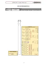
APPLICATION DIAGRAM NO.7
The diagram below can be applied to any settings of programmable outputs to setup any desired
system providing alarming, control or logic combinations functionality.
When a function is appointed to an output, it is essential that the function itself is active for the
output to work. E.g., if
“
I>>>
”
function is appointed to an output, that output will not work unless
I>>> is activated. Likewise, an output programmed as
“
Buchholz Trip
”
will never work until an input
is set as
“
Buchholz Trip
”. □
Function
Function Activation Address
Settings
Control and Alarming
via Outputs
Automatic
Output
MENU » Automatic Control Settings » Output Settings » 1-2.Output » (Any function)
Summary of Contents for CPM 311
Page 1: ......
Page 9: ... 9 INTRODUCTION ...
Page 31: ... 31 PACKING LABELING INFORMATION ...
Page 33: ... 33 OPERATING MANUAL ...
Page 49: ... 49 RELAY MENUS MANUAL ...
Page 51: ... 51 The Menu Tree ...
Page 52: ... 52 ...
Page 53: ... 53 ...
Page 54: ... 54 ...
Page 55: ... 55 ...
Page 56: ... 56 ...
Page 57: ... 57 ...
Page 124: ... 124 DIGICONNECT PC PROGRAM MANUAL ...
Page 181: ... 181 APPLICATION DIAGRAMS ...
Page 183: ... 183 Sample Power Transformer Protection Application Diagram ...
Page 185: ... 185 FUNDAMENTAL CABLING DIAGRAM ...
Page 195: ... 195 APPLICATION DIAGRAM NO 10 Function Function Activation Address RS485 Connection Settings ...
Page 196: ... 196 TECHNICAL DATA ...
Page 208: ... 208 GLOSSARY ...


