- 189 -
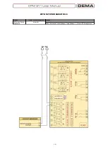
APPLICATION DIAGRAM NO.4
Function
Function Activation Address
Setting Group
Selection
Automatic
Input
MENU » Automatic Control Settings » Input Settings » 1-5.Input » Group Selection
Auto-recloser blocking
Automatic
Input
MENU » Automatic Control Settings » Input Settings » 1-5.Input » Block ARCL
Start Waveform
Record
Automatic
Input
MENU » Automatic Control Settings » Input Settings » 1-5.Input » Start Waveform Rec.
Reset Latch
Automatic
Input
tAux1
Automatic
Input
MENU » Automatic Control Settings » Input Settings » 1-5.Input » Start tAux1
tAux2
Automatic
Input
MENU » Automatic Control Settings » Input Settings » 1-5.Input » Start tAux2
MENU » Automatic Control Settings » Input Settings » 1-5.Input » Reset Latch
Reset RL1-RL2
Automatic
Input
MENU » Automatic Control Settings » Input Settings » 1-5.Input » RL1-RL2 Reset
Reset LED
Automatic
Input
MENU » Automatic Control Settings » Input Settings » 1-5.Input » Reset LED
Settings
Summary of Contents for CPM 311
Page 1: ......
Page 9: ... 9 INTRODUCTION ...
Page 31: ... 31 PACKING LABELING INFORMATION ...
Page 33: ... 33 OPERATING MANUAL ...
Page 49: ... 49 RELAY MENUS MANUAL ...
Page 51: ... 51 The Menu Tree ...
Page 52: ... 52 ...
Page 53: ... 53 ...
Page 54: ... 54 ...
Page 55: ... 55 ...
Page 56: ... 56 ...
Page 57: ... 57 ...
Page 124: ... 124 DIGICONNECT PC PROGRAM MANUAL ...
Page 181: ... 181 APPLICATION DIAGRAMS ...
Page 183: ... 183 Sample Power Transformer Protection Application Diagram ...
Page 185: ... 185 FUNDAMENTAL CABLING DIAGRAM ...
Page 195: ... 195 APPLICATION DIAGRAM NO 10 Function Function Activation Address RS485 Connection Settings ...
Page 196: ... 196 TECHNICAL DATA ...
Page 208: ... 208 GLOSSARY ...


