background image

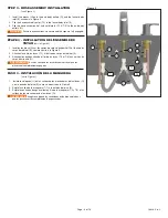
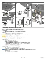
STEP 4 - DRAIN ASSEMBLY INSTALLATION 

(see Figure 4)

1. 

Flange Seal:

a.  Apply silicone to underside of flange (W). Insert flange (W) into sink drain hole.

2. 

Drain Install:

a.  Install nut (Z), washer (Y) and black gasket (X) onto body drain (AA).

b.  Thread the body drain (AA) onto the flange (W) until tight.



DO NOT 

turn flange (W) while tightening body drain (AA) or sealant may not seal drain.

c.  Tighten the nut (Z) to the under side of the sink.



DO NOT 

turn flange (W) while tightening nut (Z) or sealant may not seal drain.

d.  Remove excess sealant from around the flange (W) and the sink.
e.  Thread the tube drain (AB) into the body drain (AA) until tight.

3. 

Pivot Rod Install

a.  Insert the stopper (V) into the flange (W).

b.  The stopper (V) can be installed in two positions:

i.  Removable with the stopper (V) rotated 90o and resting on the horizontal rod (AE) (Detail 3a).

ii.  Non-removable with the horizontal rod (AE) through the hole in the stopper (V) (Detail 3b).

c.  Install washer (AC) and spacer (AD) into the pivot opening. 

d.  Install the horizontal rod (AE) into the pivot opening.
e.  Hand tighten the pivot nut (AF) onto the body drain (AA).

4. 

Lift Rod Install

a.  Attach horizontal rod (AE) to strap (AG) using clip (AH). 

b.  Install lift rod assembly (AJ) through the faucet body (A) into the strap (AG). 



The strap (AG) may need to be bent to allow the lift rod assembly (AJ) to raise and lower the stopper (V). Adjust as required.

c.  Tighten screw (AI). 

d.  Connect assembly to drain (ZB*) 

(not supplied)

.

Figure 4

Silicone / Silicona

W

X

Z

Y

W

V

AF

AE

AC

AA

AD

V

AE

1

2a

V

AE

AB

AJ

3

4

3a

3b

AA

AA

ZB*

AH

AG

A

2c

2b

AB

AA

Z

AI

AJ

* Supplied by others / Fourni par d’autres / Suministrado por otros

Page - 7 of 16

214820, Rev. C

Summary of Contents for 3534LF

Page 1: ...ter supply hook up POUR INSTALLER VOTRE ROBINET DELTA FACILEMENT VOUS DEVEZ LIRE TOUTES les instructions avant de d buter LIRE TOUS les avertissements ainsi que toutes les instructions de nettoyage et...

Page 2: ...s Centros 2 17 55mm 8 5 216mm 2 25 57mm 3x 1 125 to 1 5 27 mm to 38 mm Hole Size Taille du trou Tama o del agujero 2 0 51mm 0 28 7mm 4 25 108mm 2 0 51mm 1 2 18NPSM 2A 3 125 80mm 4 3 109mm 4 2 107mm 3...

Page 3: ...Rondelle Arandela R 2 End body mounting plate Plaque de montage du corps d extr mit Placa de montaje del cuerpo de la llave S 4 Bolt Boulon Perno T 1 Hose assembly Ensemble de tuyau Manguera T 1 1 Ho...

Page 4: ...e montage du corps d extr mit R puis vissez la plaque de montage du corps d extr mit R sur l ensemble du corps d extr mit G 6 Serrez les 2 boulons S uniform ment jusqu ce que l ensemble du corps d ext...

Page 5: ...hexagonale T1 installez les vis de r glage J pour fixer les manettes aux ensembles de corps d extr mit G Ensuite installez les boutons de manette K dans les manettes H et I pour recouvrir les vis de...

Page 6: ...e du tuyau T 1 l entr e du corps du robinet E 3 Attachez les entr es chaude et froide du tuyau T 2 et T 3 aux sorties du corps d extr mit O Assurez vous que les raccords sont serr s et que les pinces...

Page 7: ...in two positions i Removable with the stopper V rotated 90o and resting on the horizontal rod AE Detail 3a ii Non removable with the horizontal rod AE through the hole in the stopper V Detail 3b c Ins...

Page 8: ...ni PASO 4 INSTALACI N DEL MECANISMO DE DRENAJE ver la Figura 4 1 Sello del reborde a Coloque silicona en la parte de abajo de reborde W Inserte el reborde W en el orificio de drenaje del lavabo 2 Inst...

Page 9: ...nt ZF non fournies 3 l aide d une cl T5 raccordez les tuyaux d alimentation ZC ou ZD non fournis aux vannes d alimentation ZE non fournies NE PAS serrer excessivement NE PAS utiliser de ruban d tanch...

Page 10: ...obinet H et I la position OFF et r installez l a rateur F 5 V rifiez tous les raccords aux fl ches pour des fuites Serrez les conduites d alimentation si n cessaire Si vous d couvrez des fuites au niv...

Page 11: ...n del pico y Junta de la base RP101498 Handle Escutcheon Base Gasket cusson de manette et Joint de base Chapet n de la llave y Junta de la base RP100776 Block Bloc Bloque RP100777 O Ring Joint toriqu...

Page 12: ...1 3 Remplacez l ensemble de cartouche G 2 RP47422 vendu individuellement 4 R assemblez et v rifiez nouveau pour des fuites Si le robinet fuit de l ensemble de tuyau voir la Figure 7B 1 Assurez vous qu...

Page 13: ...roduct avec soin M me si son fini est extr mement durable il peut tre ab m par des produits fortement abrasifs ou des produits de polissage Il faut simplement le frotter doucement avec un chiffon humi...

Page 14: ...ervice or Replacement Parts A warranty claim may be made and replacement parts may be obtained by calling 1 800 345 DELTA 3358 or by contacting us by mail or online as follows please include your mode...

Page 15: ...i ces de rechange DeltaMD Ce que vous devez faire pour obtenir le Service sous garantie ou des pi ces de rechange Une r clamation de garantie peut tre r alis e et des pi ces de rechange peuvent tre ob...

Page 16: ...er servicio de garant a o partes de reemplazo Se puede hacer un reclamo de garant a y se pueden obtener repuestos llamando al 1 800 345 DELTA 3358 o contact ndonos por correo o por Internet de la sigu...

Reviews: