background image

VMC 186/40 Motion Control Module                                              Control Parameters 



 13 




Estop Mask (Default: FFFFH  Emergency stop disabled) 

The bits in the 

Estop Mask

 field have a one-to-one correspondence with the bits in the 

Status Word

.  The bits in 

this field are used to mask out the emergency stop that occurs when an error bit is set in the 

Status Word

.  

During an emergency stop, the drive output is immediately set to null and held there until a new command is 
issued.  To enable an emergency stop on an error condition, the appropriate bit must be 

cleared

 in both the 

Halt 

Mask

 and the 

Estop Mask

Halt Mask (Default: 0000H  HALT enabled) 

Like the 

Estop Mask, t

he bits in the 

Halt Mask

 field have a one-to-one correspondence with the bits in the 

Status Word

.  The bits in this field are used to mask out the automatic halt that occurs when an error bit is set in 

the 

Status Word

.  On start-up, this field is zero and any error will cause a halt.  For applications where two or 

more axes are moving together, the VME controller should mask out the automatic halts and take responsibility 
for handling any errors.  See the error handling section on page 30. 

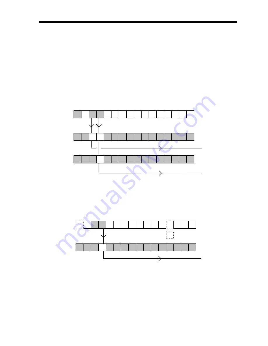
Status Word, Halt and Estop Masks

15

14

13

12

11

10

9

8

7

6

5

4

3

2

1

0

Halt Mask

15

14

13

12

11

10

9

8

7

6

5

4

3

2

1

0

Estop Mask

Axis

Emergency

Halt

Stop

= CFFF

= EFFF

Lead error causes a Halt and Overdrive causes an emergency stop

15

14

13

12

11

10

9

8

7

6

5

4

3

2

1

0

Status Word

= B000


Interrupt Mask  (Default: FFFFH  Interrupts disabled) 

The bits in the 

Interrupt Mask

 are used to selectively enable interrupts. By clearing bit 12 of the mask, the 

VMC 186/40 can generate a overdrive error interrupt when an overdrive condition is detected.  This word only 
needs to be used if the VME controller is configured to accept a bus interrupt. On start-up, this word is FFFFH. 
Therefore, all of the interrupts are disabled. 


15

14

13

12

11

10

9

8

7

6

5

4

3

2

1

0

Interrupt Mask

= EFFF

15

14

13

12

11

10

9

8

7

6

5

4

3

2

1

0

Status Word

= B000

Overdrive error causes a VME interrupt

VME
Interrupt

Will not

cause

an

interrupt


Summary of Contents for VMC 186/40

Page 1: ...by the owner Although great effort has been taken to ensure the accuracy of the information in this document it is intended to be used only as a guide Knowledge of motion control hydraulic servos ele...

Page 2: ...35 0 disabled 14 Minimum Update Time Default 1000 14 Dither Default 0 15 Hysteresis Default 0 15 Static Gain Default 50 15 Extend Gain Default 50 15 Retract Gain Default 50 15 Integral Gain Default 0...

Page 3: ...ler Error Handling 30 Key Items to Remember 30 Front Panel Indicators 31 Hardware Configuration Information 32 Supported VME Bus Address Modifiers 32 Module Jumpers and Removable Resistors 32 Magnetos...

Page 4: ...vo motors and hydraulic servo valves The VMC 186 40 occupies one slot two slots if options installed of the VME rack Programming of the VMC 186 40 is done using memory reads and writes The on board 80...

Page 5: ...ion Inputs Four optically isolated magnetostrictive transducer interfaces 1 5V return pulse sensitivity 55 5 MHz counters 1 2 or 4 recirculations 2 default Positive or negative interrogating pulse Dri...

Page 6: ...d 4CH Feed Forward Advance 0 Time shift in milliseconds for Feed Forward term 4EH Null Update 500 Null calculation interval in milliseconds 50H Minimum Update Time Axis one only 1000 Minimum time in m...

Page 7: ...Halt or Estop masks are enabled for a parameter error the axis will not move Target Position The Target Position is the calculated position where the axis should be at any moment When the axis is mov...

Page 8: ...osition 0 At Command Position 2 Halted 3 Accelerating 4 At Requested Speed 5 Decelerating 6 Stopped 7 Active 8 Parameter Error 9 Position Overflow 10 Tranducer Not Responding 11 Valve Out of Null 12 O...

Page 9: ...2000 Transducer Counts per second This bit is intended for use as an axis obstruction indication It is not latched Bit 7 Active This bit will toggle while the motion controller module is running axis...

Page 10: ...the 12 bit range of the A D converter Usually this error is an indication the system does not have enough power to drive the axis at the requested speed The computer will truncate the drive to 12 bits...

Page 11: ...0 1 1 0 0 1 1 0 5 0 1 0 1 0 1 0 1 0 1 0 1 0 1 0 1 4 0 1 0 0 0 1 0 0 0 1 0 0 0 1 0 0 3 0 0 1 1 0 0 1 1 0 0 1 1 0 0 1 1 2 0 0 1 0 0 0 1 0 0 0 1 0 0 0 1 0 1 0 0 0 1 0 0 0 1 0 0 0 1 0 0 0 1 0 0 0 0 0 0 0...

Page 12: ...ing 16 bit counter On axis two the toggle interval for the Status Word s Active bit is programmed The toggle interval can be programmed from 0 to 65535 If programmed with a 0 a one millisecond interva...

Page 13: ...or applications where two or more axes are moving together the VME controller should mask out the automatic halts and take responsibility for handling any errors See the error handling section on page...

Page 14: ...n the target position the value of null drive is decreased by one If the actual position is less than the target position the value of null drive is increased by one This minimum value depends on the...

Page 15: ...llate See Maximum Position Error parameter on page 19 CAUTION Increase the Static Gain slowly Excessive gain can cause oscillations that could damage both man and machine Extend Gain Default 50 Extend...

Page 16: ...ward is too small or the system response is too slow If lead errors occur the feed forward is too big or the system response is too slow The F command used after an extend move on the axis will automa...

Page 17: ...number must be specified in the same base units as the position units inches mm etc If the calibration number is expressed in inches then position units would be expressed in inches i e 9 1392 micros...

Page 18: ...limeter and one recirculation the Scale will be found as follows 32768 Scale 16642 003937 1mm 9 0110 55 5 1 Fine tuning for example 2 Measured Position 1 1 meter 10 000 position units Position Reading...

Page 19: ...o Proportional Gain Maximum Position Error Maximum Proportional Drive 100 Proportional Gain represents the Extend or Retract Gain parameters At Command Position Default 50 At Command Position specifie...

Page 20: ...used This mode only affects the drive the VMC 186 40 still expects to see the transducer counts decrease when retracting even through the drive will be positive when retracting BIT 3 Simulator When s...

Page 21: ...s sec sec If Scale were set so one position unit equaled 0 001 then a value of 200 would represent an acceleration rate of 200 inches sec sec Using ramping distance expressed in position units is simp...

Page 22: ...go to the Requested Position H Halt 48H 72 The Halt command is used for emergency stops jogging the axis or when the drive power is off If the axis is moving and an H is used the axis will ramp down u...

Page 23: ...0 of full negative drive 64511 decimal Command 79 O Results in a drive value of 1024 null 1024 Prior to August of 1992 the Override command would put the axis into a mode in which only counts and serv...

Page 24: ...r of recirculations can be selected in hardware by the proper selection of jumpers P8 P11 Normally two recirculations are used See page 33 for more information on recirculations Drive Output The drive...

Page 25: ...ented at a rate calculated to bring the value to zero when the axis stops The drive provided by the integrator is given by Integral Gain Accumulator Integral Drive 20 000 The differentiator looks at t...

Page 26: ...is an error a count will be added until it is corrected If the differential gain is set to a value greater then zero the differentiator will affect the drive when the axis is at rest See page 25 for...

Page 27: ...he drive output from the VMC 186 40 15 pin connector and establish a means of moving the axis under manual control Using some type of memory monitor DCSMON monitor the appropriate memory locations Mak...

Page 28: ...s to determine what caused the error Increase the speed and accelerations slowly while making longer moves Use DCSMON to make plots of the moves and look for lead lag overshoot or oscillations Eventua...

Page 29: ...the hunting stops or the axis starts to oscillate If oscillations occur reduce the Hysteresis 12 The Null Update should not be used until the Hysteresis is adjusted Try to keep the Null Update interva...

Page 30: ...the axes will stop If an error occurs on the VMC 186 40 the contact can be deactivated thus stopping the axes Usually the VME Controller will not take so drastic a step until it has determined that a...

Page 31: ...flash red repetitively until a new command is used Note If a transducer fails to respond the output to the corresponding axis will be set to the current drive null and its LED will be red If the axis...

Page 32: ...stors RF Resistor fuses for transducer power page 41 R1 R4 Sockets for 100 resistors when installed convert current outputs to 10 volts page 38 P4 P7 Select transducer interrogation pulse polarity pag...

Page 33: ...axis 1 negative pulse P6 2 3 axis 3 negative pulse P5 1 2 axis 2 positive pulse P7 1 2 axis 4 positive pulse P5 2 3 axis 2 negative pulse P7 2 3 axis 4 negative pulse 1 2 3 1 2 3 P4 P5 1 2 3 1 2 3 P6...

Page 34: ...Measurement Time 750mm Maximum Usable Transducer Resolution 1 3293mm 269us 0502mm 2 1647mm 537us 0251mm 4 823mm 1075us 0126mm CAUTION The longest measurement time should never exceed 1000 microseconds...

Page 35: ...umpers allow the dual port memory to be placed anywhere in the 16 megabyte address space The upper 15 address lines are used to select the dual port RAM which always starts on a 512 byte boundary With...

Page 36: ...ult for restart When jumper P12 is installed the 60 millisecond fail safe timer is connected to the board reset Normally the fail safe timer is reset every millisecond If the processor fails to reset...

Page 37: ...Note The status ID byte is transferred using odd address low data bus D08 O VME bus conventions During the interrupt acknowledge cycle the VME Controller will indicate which IRQ line it is responding...

Page 38: ...the 100mA output to a lower full scale current This allows the maximum output resolution of the VMC 186 40 board to be utilized with valves of less than full scale output Use of the network will also...

Page 39: ...connect the drive outputs to the drives until the limits have been computed and VMC 186 40 properly initialized with these limits using the VME controller Delta Computer Systems Inc supplies two cabl...

Page 40: ...tion s drive inputs to the DB15 front panel connector uses the following color code PIN Function Wire Color 1 15 input RED 2 Power Supply Common BLACK 3 15 input WHITE 4 Common GREEN 5 Drive Out 1 ORA...

Page 41: ...10 to determine if the module is detecting a transducer error To reduce electrical noise check the following a Make sure the transducer wiring is separated from all other wiring b Add a termination r...

Page 42: ...ent for an RMA number Returned modules should be packaged in static protection material and the RMA number clearly marked on the outside of package Please include a short note explaining the problem S...

Page 43: ...ousandths of an inch tenths of millimeters thousandths of revolutions etc Position units are calculated by using scale and transducer counts Recirculation The number of times a magnetostrictive transd...

Page 44: ...Hex SP 32 20 33 21 34 22 35 23 36 24 37 25 38 26 39 27 40 28 41 29 42 2A 43 2B 44 2C 45 2D 46 2E 47 2F 0 48 30 1 49 31 2 50 32 3 51 33 4 52 34 5 53 35 6 54 36 7 55 37 8 56 38 9 57 39 58 3A 59 3B 60 3C...

Page 45: ...VMC 186 40 Motion Controller Appendix B 45 External Wiring Examples...

Reviews: