Model 9330-150-A01 Installation Instructions
Page 13 of 16
Document: INS-9330-A01, Rev. C
Do not copy or distribute without written permission. Unpublished Work
2022 Delphi Display Systems, Inc. All rights reserved.
Printed copies are Uncontrolled unless clearly marked as a Controlled document. User is responsible for verifying document is the current revision.
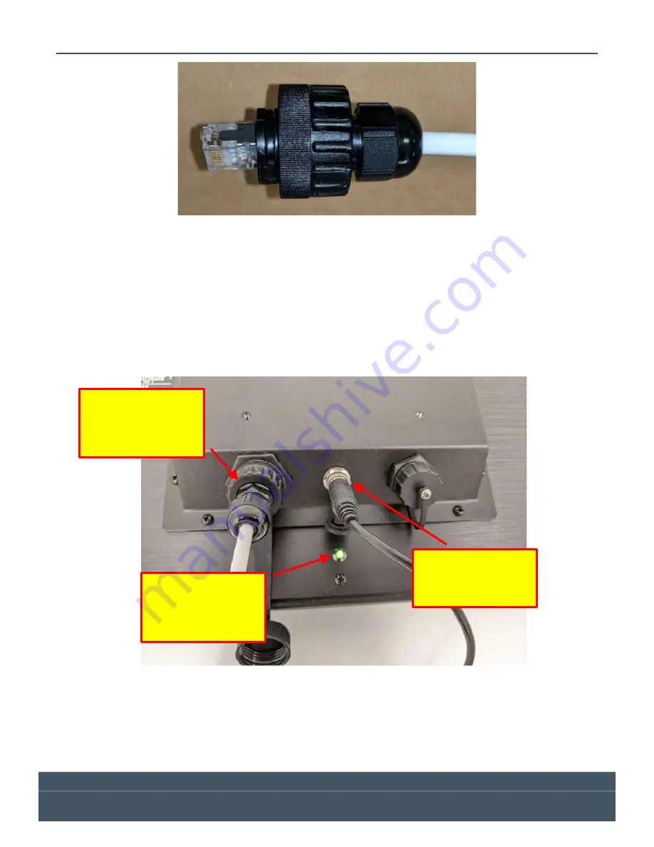
Figure 13 - Field Connector Assembly Step 4
6.2
Connecting Power and Data to the Display
The water-proof RJ45 connector is now ready for connection to the display. Plug the connector to the back
of the display at the RJ45 receptacle. Once connected, screw the “Connector Nut” into the back of the
display until it is tight.
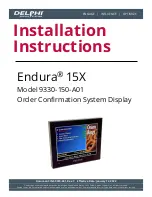
Connect the +15V power supply output cable barrel connector to the power input connector on the back of
the display as shown below. BE SURE to lock the connector in place using the locking ring so it will maintain
a secure and watertight connection. Apply AC power and verify that the power indicator illuminates.
Figure 14 – Display Data and Power Connections
Verify that the
power indicator
light is on when
power is applied
Tighten Locking
Ring on DC Power
Connector
Tighten Locking
Ring on Ethernet
Connector


