Model 9330-150-A01 Installation Instructions
Page 12 of 16
Document: INS-9330-A01, Rev. C
Do not copy or distribute without written permission. Unpublished Work
2022 Delphi Display Systems, Inc. All rights reserved.
Printed copies are Uncontrolled unless clearly marked as a Controlled document. User is responsible for verifying document is the current revision.
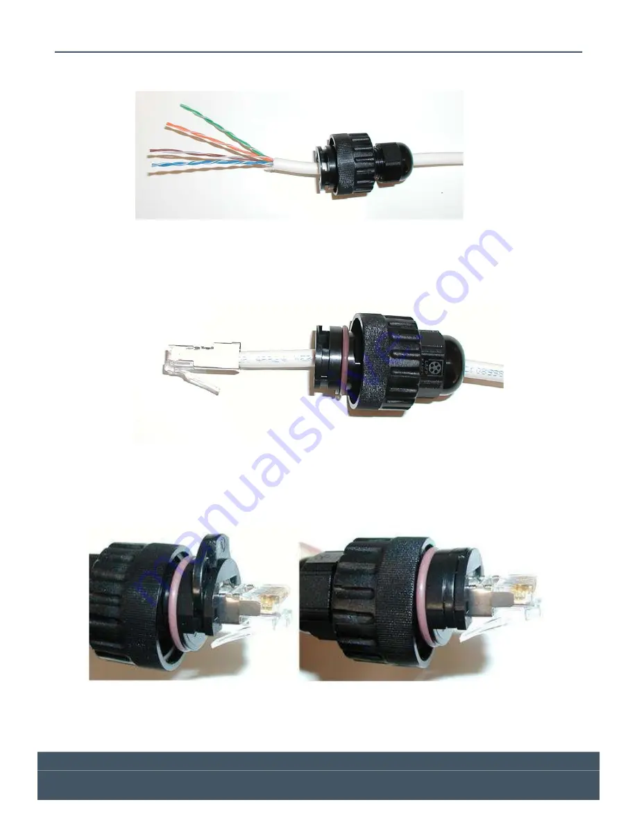
Next, strip the jacket from the end of the CAT5E cable, and put the parts together loosely (do not tighten) as
shown below.
Figure 11 - Field Connector Assembly Step 2
Next, untwist the wires and place them into the correct order for
568B
termination. Cut the length of the
wires down to approximately ½” (13mm), then terminate the cable with the supplied shielded RJ45
connector as shown below.
Figure 12 - Field Connector Assembly Step 3
Slide the housing up the cable until the RJ45 connector is seated into the housing. Place one of the two
supplied retainer clips (the other one is a spare) into the slot and ensure it is clipped into place as shown
below.
Lastly, tighten the compression nut and the assembly is complete. The completed connector should look
like the one pictured below.


