


9. Remove the two (M2x5) screws that secure the USB Type-C bracket to the system board.
10. Remove the two (M2x2) screws and one (M2x4) screw that secures the system board to the palm-rest and keyboard
assembly.
11. Lift the system board off the palm-rest and keyboard assembly.
Installing the system board
Prerequisites
If you are replacing a component, remove the existing component before performing the installation procedure.
About this task
NOTE:
When replacing/accessing other parts, the system board can be installed with the heat sink attached in order to
simplify the procedure and preserve the thermal bond between the system board and heat-sink.
NOTE:
Your computer’s Service Tag is stored in the system board. You must enter the Service Tag in the BIOS setup
program after you replace the system board.
NOTE:
Replacing the system board removes any changes you have made to the BIOS using the BIOS setup program. You
must make the appropriate changes again after you replace the system board.
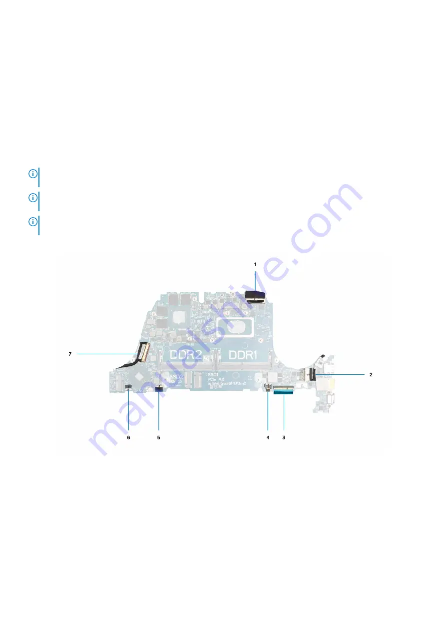
The following image indicates the connectors on your system board.
Figure 2. System board connectors
1. Display cable connector
2. Power-adapter port cable connector
3. Keyboard cable connector
4. Keyboard backlit cable connector
5. Touchpad cable connector
6. I/O-board cable connector
7. Speaker cable connector
The following image indicates the location of the system board and provides a visual representation of the installation procedure.
60
Removing and installing components


