background image

Installing the wireless card

Prerequisites

If you are replacing a component, remove the existing component before performing the installation procedure.

About this task

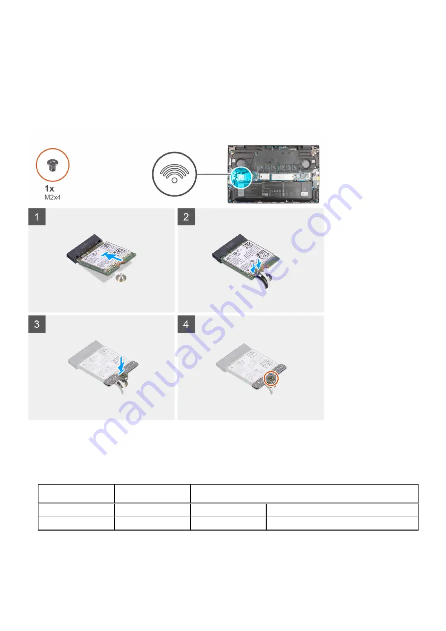
The following image indicates the location of the wireless card and provides a visual representation of the installation procedure.

Steps

1. Connect the antenna cables to the wireless card.

The following table provides the antenna-cable color scheme for the wireless card that is supported by your computer.

Table 2. Antenna-cable color scheme 

Connectors on the

wireless card

Antenna-cable color

Silkscreen marking

Main

White

MAIN

 (white triangle)

Auxiliary

Black

AUX

 (black triangle)

2. Align the notch on the wireless card with the tab on the wireless-card slot on the system board.
3. Slide and insert the wireless card at an angle into the wireless-card slot on the system board.
4. Align the screw hole on the wireless-card bracket to the screw hole on the wireless card and system board.

Removing and installing components

33

Summary of Contents for Vostro 15 7510

Page 1: ...Vostro 15 7510 Service Manual Regulatory Model P106F Regulatory Type P106F002 June 2021 Rev A00 ...

Page 2: ...ential damage to hardware or loss of data and tells you how to avoid the problem WARNING A WARNING indicates a potential for property damage personal injury or death 2021 Dell Inc or its subsidiaries All rights reserved Dell EMC and other trademarks are trademarks of Dell Inc or its subsidiaries Other trademarks may be trademarks of their respective owners ...

Page 3: ...he memory module 23 Installing the memory module 24 Solid state drive M 2 slot one 26 Removing the 2230 solid state drive from M 2 slot one 26 Installing the 2230 solid state drive in M 2 slot one 27 Removing the 2280 solid state drive from M 2 slot one 28 Installing the 2280 solid state drive in M 2 slot one 29 Solid state drive M 2 slot two 30 Removing the 2230 solid state drive from M 2 slot tw...

Page 4: ...ng the power button with fingerprint reader 54 Power adapter port 55 Removing the power adapter port 55 Installing the power adapter port 56 System board 57 Removing the system board 57 Installing the system board 60 Palm rest and keyboard assembly 62 Removing the palm rest and keyboard assembly 62 Installing the palm rest and keyboard assembly 63 Chapter 3 Drivers and downloads 65 Downloading the...

Page 5: ...81 Running the SupportAssist Pre Boot System Performance Check 81 System diagnostic lights 81 Recovering the operating system 83 Real Time Clock RTC Reset 83 Flashing BIOS USB key 83 Flashing the BIOS 83 Backup media and recovery options 84 WiFi power cycle 84 Flea power release 84 Chapter 6 Getting help 85 Contacting Dell 85 Contents 5 ...

Page 6: ...d by Dell is not covered by your warranty See the safety instructions that is shipped with the product or at www dell com regulatory_compliance CAUTION Before touching anything inside your computer ground yourself by touching an unpainted metal surface such as the metal at the back of the computer While you work periodically touch an unpainted metal surface to dissipate static electricity which co...

Page 7: ...ailures means that most of the time when damage occurs it is not immediately recognizable The DIMM receives a static shock but the tracing is merely weakened and does not immediately produce outward symptoms related to the damage The weakened trace may take weeks or months to melt and in the meantime may cause degradation of memory integrity intermittent memory errors etc The more difficult type o...

Page 8: ...meters away from sensitive parts before physically handling any hardware components ESD Packaging All ESD sensitive devices must be shipped and received in static safe packaging Metal static shielded bags are preferred However you should always return the damaged part using the same ESD bag and packaging that the new part arrived in The ESD bag should be folded over and taped shut and all the same...

Page 9: ... on the computer Your computer will automatically return to normal functioning mode After working inside your computer About this task CAUTION Leaving stray or loose screws inside your computer may severely damage your computer Steps 1 Replace all screws and ensure that no stray screws remain inside your computer 2 Connect any external devices peripherals or cables you removed before working on yo...

Page 10: ...reader Power adapter port System board Palm rest and keyboard assembly Recommended tools The procedures in this document may require the following tools Phillips screwdriver 0 Phillips screwdriver 1 Plastic scribe Screw list NOTE When removing screws from a component it is recommended to note the screw type the quantity of screws and then place them in a screw storage box This is to ensure that th...

Page 11: ... Slot 1 M2x4 1 Solid state drive Slot 2 M2x4 1 GPU Fan M2x4 2 System Fan M2x4 2 Heat sink Captive screws 7 System board M2x2 M2x4 2 1 USB Type C bracket M2x5 2 Power button M2x4 1 Power button with fingerprint reader M2x4 1 I O board M2x4 2 Touchpad M2x1 8 M2x3 5 2 Power adapter port M2 5x5 2 Display assembly M2 5x5 4 Removing and installing components 11 ...

Page 12: ...Major components of your system 1 Base cover 2 Heat sink 3 System fan 4 Memory module 5 Power adapter port 6 M 2 2280 SSD card 7 System board 12 Removing and installing components ...

Page 13: ...stem configuration purchased These parts are available according to warranty coverages purchased by the customer Contact your Dell sales representative for purchase options Base cover Removing the base cover Prerequisites 1 Follow the procedure in Before working inside your computer 2 Enter Service Mode About this task The following images indicate the location of the base cover and provide a visu...

Page 14: ...14 Removing and installing components ...

Page 15: ...Removing and installing components 15 ...

Page 16: ...continue to work on the sides to release the base cover from the palm rest and keyboard assembly 4 Disconnect the battery cable 5 Lift the base cover off the palm rest and keyboard assembly Installing the base cover Prerequisites If you are replacing a component remove the existing component before performing the installation procedure About this task The following images indicate the location of ...

Page 17: ...Removing and installing components 17 ...

Page 18: ...18 Removing and installing components ...

Page 19: ...se caution when handling Lithium ion batteries Discharge the battery completely before removing it Disconnect the AC power adapter from the system and operate the computer solely on battery power the battery is fully discharged when the computer no longer turns on when the power button is pressed Do not crush drop mutilate or penetrate the battery with foreign objects Do not expose the battery to ...

Page 20: ...equisites 1 Follow the procedure in Before working inside your computer 2 Remove the base cover About this task NOTE Vostro 15 7510 also supports 6 cell 86 Wh battery NOTE Inspiron 15 7510 also supports 6 cell 86 Wh battery The following image indicates the location of the 3 cell 56 Wh battery and provides a visual representation of the removal procedure Steps 1 Disconnect the battery cable from t...

Page 21: ...les on the palm rest and keyboard assembly 3 Replace the five M2x3 screws that secure the 3 cell battery to the palm rest and keyboard assembly 4 Connect the battery cable to the system board Next steps 1 Install the base cover 2 Follow the procedure in After working on your computer Battery cable Removing the battery cable Prerequisites 1 Follow the procedure in Before working inside your compute...

Page 22: ...isconnect the battery cable from the connector on the battery 3 Lift the battery cable off the battery Installing the battery cable Prerequisites If you are replacing a component remove the existing component before performing the installation procedure About this task The following image indicates the location of the battery cable and provides a visual representation of the installation procedure...

Page 23: ...re in After working on your computer Memory Removing the memory module Prerequisites 1 Follow the procedure in Before working inside your computer 2 Enter Service Mode 3 Remove the base cover About this task NOTE Vostro 15 7510 supports two memory slots NOTE Inspiron 15 7510 supports two memory slots The following images indicate the location of the memory module and provide a visual representatio...

Page 24: ...t NOTE Repeat step 1 to step 3 to remove any other memory module installed in your computer Installing the memory module Prerequisites If you are replacing a component remove the existing component before performing the installation procedure About this task NOTE Vostro 15 7510 supports two memory slots NOTE Inspiron 15 7510 supports two memory slots 24 Removing and installing components ...

Page 25: ...module slot 3 Slide the memory module firmly at an angle into the memory module slot 4 Press the memory module down until it clicks into place NOTE If you do not hear the click remove the memory module and reinstall it NOTE Repeat step 1 to step 4 to install any other memory modules in your computer Next steps 1 Install the base cover 2 Exit Service Mode 3 Follow the procedure in After working ins...

Page 26: ...NOTE If you have ordered a system with M 2 2280 solid state drive in M 2 slot one and want to replace it with a M 2 2230 solid state drive you will need a mounting bracket sold separately please contact Dell support NOTE This procedure applies only to computers shipped with a 2230 solid state drive installed in M 2 slot one The following image indicates the location of the 2230 solid state drive t...

Page 27: ...parately please contact Dell support NOTE This procedure applies only if you are installing a 2230 solid state drive in M 2 slot one The following image indicates the location of the 2230 solid state drive that is installed in M 2 slot one and provides a visual representation of the installation procedure Steps 1 Slide and place the solid state drive mounting bracket to accommodate the 2230 solid ...

Page 28: ...rd configurations on M 2 slot one M 2 2230 solid state drive M 2 2230 mounting bracket M 2 2280 solid state drive NOTE If you have ordered a system with M 2 2280 solid state drive in M 2 slot one and want to replace it with a M 2 2230 solid state drive you will need a mounting bracket sold separately please contact Dell support NOTE This procedure applies only to computers shipped with a 2280 soli...

Page 29: ...nt to replace it with a M 2 2230 solid state drive you will need a mounting bracket sold separately please contact Dell support NOTE This procedure is applicable if you are installing a 2280 solid state drive in M 2 slot one NOTE When installing a M 2 2280 NVMe Gen4 0 x4 solid state drive you may order a copper thermal shield from Dell support for better thermal performance The following image ind...

Page 30: ...procedure applies only to computers shipped with a 2230 solid state drive installed in M 2 slot two 1 Follow the procedure in Before working inside your computer NOTE Solid state drives are fragile Exercise care when handling the solid state drive NOTE To avoid data loss do not remove the solid state drive while the computer is in sleep or on state 2 Enter Service Mode 3 Remove the base cover Abou...

Page 31: ...re applies only to computers shipped with a 2230 solid state drive installed in M 2 slot two The following image indicates the location of the 2230 solid state drive that is installed in M 2 slot two and provides a visual representation of the installation procedure Steps 1 Align the notch on the 2230 solid state drive with the tab on M 2 slot two on the system board 2 Slide the solid state drive ...

Page 32: ...s task The following images indicate the location of the wireless card and provide a visual representation of the removal procedure Steps 1 Remove the screw M2x4 that secures the wireless card bracket to the wireless card and system board 2 Remove the wireless card bracket from the wireless card 3 Disconnect the antenna cables from the wireless card 4 Slide and remove the wireless card from the wi...

Page 33: ...nna cable color scheme for the wireless card that is supported by your computer Table 2 Antenna cable color scheme Connectors on the wireless card Antenna cable color Silkscreen marking Main White MAIN white triangle Auxiliary Black AUX black triangle 2 Align the notch on the wireless card with the tab on the wireless card slot on the system board 3 Slide and insert the wireless card at an angle i...

Page 34: ...er 2 Enter Service Mode 3 Remove the base cover About this task The figure indicates the location of the GPU fan and provides a visual representation of the removal procedure Steps 1 Flip the Mylar cover open 2 Disconnect the GPU fan cable from the system board 3 Remove the two M2x4 screws that secure the GPU fan to the palm rest and keyboard assembly 4 Unroute the I O cable from routing guides un...

Page 35: ...r 2 Route the I O cable through the routing guides underneath the GPU fan 3 Slide and place the GPU fan on the palm rest and keyboard assembly 4 Align the screw holes on the GPU fan with the screw holes on the palm rest and keyboard assembly 5 Replace the two M2x4 screws to secure the GPU fan to the palm rest and keyboard assembly 6 Connect the GPU fan cable to the system board Next steps 1 Instal...

Page 36: ...ct the fan cable from the system board 2 Remove the two M2x4 screws that secure the fan to the palm rest and keyboard assembly 3 Lift the fan off the palm rest and keyboard assembly Installing the system fan Prerequisites If you are replacing a component remove the existing component before performing the installation procedure About this task The following image indicates the location of the fan ...

Page 37: ...ide your computer Heat sink Removing the heat sink Prerequisites 1 Follow the procedure in Before working inside your computer CAUTION For maximum cooling of the processor do not touch the heat transfer areas on the heat sink The oils in your skin can reduce the heat transfer capability of the thermal grease NOTE The heat sink may become hot during normal operation Allow sufficient time for the he...

Page 38: ...ng the heat sink Prerequisites If you are replacing a component remove the existing component before performing the installation procedure CAUTION Incorrect alignment of the heat sink can damage the system board and processor NOTE If either the system board or the heat sink is replaced use the thermal pad paste provided in the kit to ensure that thermal conductivity is achieved About this task The...

Page 39: ...nstall the base cover 2 Exit Service Mode 3 Follow the procedure in After working inside your computer I O board Removing the I O board Prerequisites 1 Follow the procedure in Before working inside your computer 2 Enter Service Mode 3 Remove the base cover 4 Remove the GPU fan About this task The following images indicate the location of the I O board and provide a visual representation of the rem...

Page 40: ...ecuring the I O board to the palm rest and keyboard assembly 6 Remove the two M2x4 screws that secure the I O board to the palm rest and keyboard assembly 7 Lift the I O board off the palm rest and keyboard assembly Installing the I O board Prerequisites If you are replacing a component remove the existing component before performing the installation procedure About this task The following image i...

Page 41: ...e to the I O board 6 Connect the I O board cable to the I O board and close the latch to secure the cable 7 Adhere the tape that secures the I O board cable to the I O board 8 Adhere the adhesive tape that secures the I O board to the palm rest and keyboard assembly Next steps 1 Install the GPU fan 2 Install the base cover 3 Exit Service Mode 4 Follow the procedure in After working inside your com...

Page 42: ...g guides on the palm rest and keyboard assembly 3 Disconnect the speaker cable from the system board 4 Lift the speakers along with the cable off the palm rest and keyboard assembly Installing the speakers Prerequisites If you are replacing a component remove the existing component before performing the installation procedure About this task The following image indicates the location of the speake...

Page 43: ...palm rest and keyboard assembly Next steps 1 Install the system board 2 Install the battery 3 Install the base cover 4 Exit Service Mode 5 Follow the procedure in After working inside your computer Touchpad Removing the touchpad Prerequisites 1 Follow the procedure in Before working inside your computer 2 Remove the base cover 3 Remove the battery About this task The following images indicate the ...

Page 44: ...e two M2x1 8 screws that secure the touchpad to the palm rest and keyboard assembly 6 Peel the tape that secures the speaker cable to the touchpad bracket 7 Lift the touchpad along with the touchpad cable off the palm rest and keyboard assembly Installing the touchpad Prerequisites If you are replacing a component remove the existing component before performing the installation procedure About thi...

Page 45: ... is equally aligned along all four sides 2 Replace the two M2x1 8 screws that secure the touchpad to the palm rest and keyboard assembly 3 Adhere the tapes that secure the touchpad to the palm rest and keyboard assembly NOTE Adhere the tapes back to its original position so that it runs across touchpad and palmrest Removing and installing components 45 ...

Page 46: ... palm rest and keyboard assembly 8 Adhere the tape that secures the speaker cable to the touchpad Next steps 1 Install the battery 2 Install the base cover 3 Follow the procedure in After working inside your computer Display assembly Removing the display assembly Prerequisites 1 Follow the procedure in Before working inside your computer 2 Enter Service Mode 3 Remove the base cover 4 Remove the he...

Page 47: ...Removing and installing components 47 ...

Page 48: ...e display hinges at an angle of 90 degrees 5 Gently slide the palm rest and keyboard assembly off the display assembly Installing the display assembly Prerequisites If you are replacing a component remove the existing component before performing the installation procedure About this task The following image indicates the location of the display assembly and provides a visual representation of the ...

Page 49: ...e display hinges 3 Replace the two M2 5x5 screws that secure the right display hinge to the system board 4 Replace the two M2 5x5 screws that secure the left display hinge to the system board 5 Slide the display cable into the connector on the system board Next steps 1 Install the heat sink 2 Install the base cover Removing and installing components 49 ...

Page 50: ...this task The following images indicate the location of the power button board and provide a visual representation of the removal procedure Steps 1 Disconnect the power button cable from the I O board 2 Peel the adhesive tape securing the power button cable to palm rest and keyboard assembly 3 Remove the screw M2x4 that secures the power button board with the cable to the palm rest and keyboard as...

Page 51: ...the power button board with the cable to the palm rest and keyboard assembly 3 Connect the power button cable to the I O board Next steps 1 Install the heat sink 2 Install the GPU fan 3 Install the base cover 4 Exit Service Mode 5 Follow the procedure in After working inside your computer Power button with optional fingerprint reader Removing the power button with optional fingerprint reader Prere...

Page 52: ...gerprint reader to the palm rest and keyboard assembly 2 Lift the power button with optional fingerprint reader off the palm rest and keyboard assembly Installing the power button with optional fingerprint reader Prerequisites If you are replacing a component remove the existing component before performing the installation process About this task The following image indicates the location of the p...

Page 53: ...e power button board 2 Install the heat sink 3 Install the GPU fan 4 Install the base cover 5 Exit Service Mode 6 Follow the procedure in After working inside your computer Power button with fingerprint reader Removing the power button with fingerprint reader Prerequisites 1 Follow the procedure in Before working inside your computer 2 Enter Service Mode 3 Remove the base cover 4 Remove the heat s...

Page 54: ...w M2x4 that secures the power button with fingerprint reader to the palm rest and keyboard assembly 3 Lift the power button with fingerprint reader along with the cable off the palm rest and keyboard assembly Installing the power button with fingerprint reader About this task The following images indicate the location of the power button with fingerprint reader and provide a visual representation ...

Page 55: ...th fingerprint reader cable to the I O board Next steps 1 Install the power button board 2 Install the heat sink 3 Install the GPU fan 4 Install the base cover 5 Exit Service Mode 6 Follow the procedure in After working inside your computer Power adapter port Removing the power adapter port Prerequisites 1 Follow the procedure in Before working inside your computer 2 Enter Service Mode 3 Remove th...

Page 56: ...the power adapter port cable to the system board 5 Remove the power adapter port cable from the routing guide on the palm rest and keyboard assembly 6 Lift the power adapter port along with its cable off the palm rest and keyboard assembly Installing the power adapter port Prerequisites If you are replacing a component remove the existing component before performing the installation procedure Abou...

Page 57: ...rd assembly Next steps 1 Install the heat sink 2 Install the base cover 3 Exit Service Mode 4 Follow the procedure in After working inside your computer System board Removing the system board Prerequisites 1 Follow the procedure in Before working inside your computer NOTE Your computer s Service Tag is stored in the system board You must enter the Service Tag in the BIOS setup program after you re...

Page 58: ...stem board can be removed and installed with the heat sink attached in order to simplify the procedure and preserve the thermal bond between the system board and heat sink The following image indicates the connectors on your system board Figure 1 System board connectors 1 Display cable connector 2 Power adapter port cable connector 3 Keyboard cable connector 4 Keyboard backlit cable connector 5 To...

Page 59: ...tem board 4 Disconnect the speaker cable from the system board 5 Open the latch and disconnect the touchpad cable from the system board 6 Open the latch and disconnect the keyboard backlit cable from the system board 7 Open the latch and disconnect the keyboard cable from the system board 8 Peel the tape and disconnect the power adapter port cable from the system board Removing and installing comp...

Page 60: ... and heat sink NOTE Your computer s Service Tag is stored in the system board You must enter the Service Tag in the BIOS setup program after you replace the system board NOTE Replacing the system board removes any changes you have made to the BIOS using the BIOS setup program You must make the appropriate changes again after you replace the system board The following image indicates the connectors...

Page 61: ...e latch to secure the cable 4 Adhere the tape that secures the display cable to the system board 5 Connect the power adapter port cable to the system board 6 Adhere the tape that secures the power adapter port cable to the system board 7 Align the screw holes on the USB Type C port bracket with the screw holes on the system board 8 Replace the two M2x5 screws that secure the USB Type C port bracke...

Page 62: ...t and keyboard assembly Removing the palm rest and keyboard assembly Prerequisites 1 Follow the procedure in Before working inside your computer 2 Remove the base cover 3 Remove the battery 4 Remove the memory module 5 Remove the M 2 2280 solid state drive or M 2 2230 solid state drive from M 2 slot one whichever applicable 6 Remove the M 2 2230 solid state drive from M 2 slot two if applicable 7 ...

Page 63: ...sembly Prerequisites If you are replacing a component remove the existing component before performing the installation procedure About this task Place the palm rest and keyboard assembly on a flat surface Removing and installing components 63 ...

Page 64: ...d NOTE The system board can be installed along with the heat sink 9 Install the I O board 10 Install the heat sink 11 Install the GPU fan 12 Install the system fan 13 Install the wireless card 14 Install the M 2 2280 solid state drive or M 2 2230 solid state drive in M 2 slot one whichever applicable 15 Install the M 2 2230 solid state drive in M 2 slot two if applicable 16 Install the memory modu...

Page 65: ... for browser specific instructions 8 Click View Drivers for My System 9 Click Download and Install to download and install all driver updates detected for your computer 10 Select a location to save the files 11 If prompted approve requests from User Account Control to make changes on the system 12 The application installs all drivers and updates identified NOTE Not all files can be installed autom...

Page 66: ...BIOS setup program Navigation keys Boot Sequence System setup options Advanced or Engineering configurations SupportAssist system resolution Updating the BIOS in Windows System and setup password BIOS overview The BIOS manages data flow between the computer s operating system and attached devices such as hard disk video adapter keyboard mouse and printer Entering BIOS setup program About this task...

Page 67: ...section may or may not be displayed Table 3 System setup options System information menu Overview BIOS Version Displays the BIOS version number Service Tag Displays the Service Tag of the computer Asset Tag Displays the Asset Tag of the computer Ownership Tag Displays the ownership tag of the computer Manufacture Date Displays the manufacture date of the computer Ownership Date Displays the owners...

Page 68: ...memory installed in the second DIMM slot Device Information Panel Type Displays the Panel Type of the computer Video Controller Displays the graphics information of the computer Video Memory Displays the video memory information of the computer Video BIOS Version Displays the video BIOS version of the computer Native Resolution Native Resolution Audio Controller Audio Controller Wi Fi Device Wi Fi...

Page 69: ...ernal Speaker Enables or disables internal speaker Default ON USB Thunderbolt Configuration Enable External USB Ports Enables or disables USB ports to be functional in an operating system environment Default ON Enable USB Boot Support Enables or disables booting from USB mass storage devices such as external hard drive optical drive and USB drive Default ON Enable Thunderbolt Boot Support Enables ...

Page 70: ... Storage Display Brightness Brightness on battery power Sets the screen brightness when the computer is running on battery power Brightness on AC power Sets the screen brightness when the computer is running on AC power Full Screen Logo Displays full screen logo if the image matches screen resolution Default OFF Table 8 System setup options Connection menu Connection Wireless Device Enable Enable ...

Page 71: ... Power Off Default OFF Enable on Dell USB C Dock Enables the Dell USB C Dock when connected to wake the computer from Standby mode Hibernate and Power Off Default ON Block Sleep Blocks the computer from entering Sleep S3 mode in the operating system Default OFF NOTE If enabled the computer will not go to sleep Intel Rapid Start will be disabled automatically and the operating system power option w...

Page 72: ...nently disable the BIOS module interface of the optional Absolute Persistence Module service from Absolute software By default the Enable Absolute option is enabled UEFI Boot Path Security Controls whether or not the computer will prompt the user to enter the admin password if set when booting to a UEFI boot device from the F12 boot menu By default the Always Except Internal HDD option is enabled ...

Page 73: ...ry menu Update Recovery UEFI Capsule Firmware Updates Enable or disable BIOS updates through UEFI capsule update packages By default the option is enabled BIOS Recovery from Hard Drive Enables the user to recover from certain corrupted BIOS conditions from a recovery file on the user primary hard drive or an external USB key By default the option is enabled BIOS Downgrade Allow BIOS Downgrade Enab...

Page 74: ...ard illumination Allows you to set Keyboard illumination settings By default the Bright option is enabled Keyboard Backlight Timeout on AC Defines the timeout value for keyboard backlight when AC adapter is plugged into the system By default the option 1 minute is enabled Keyboard Backlight Timeout on Battery Defines the timeout value for keyboard backlight when the system is running only on syste...

Page 75: ...o dynamically adjust processor voltage and core frequency decreasing average power consumption and heat production By default the option is enabled C States Control Enable C State Control Enable or disable additional processor sleep states By default the option is enabled Enable Adaptive C States for Discrete Graphics Adaptive C states will allow for the system to dynamically detect high usage of ...

Page 76: ...e LinkSpeed Auto Default Gen 1 Gen 2 Gen 3 SupportAssist system resolution Table 20 SupportAssit System Resolution Option Description Auto OS Recovery Threshold The Auto OS Recovery Threshold setup option controls the automatic boot flow for Support Assist System Resolution Console and Dell OS Recovery tool Choose one of the following options OFF 1 2 Default 3 SupportAssist OS Recovery Allows you ...

Page 77: ... BIOS file and click Download 10 Select your preferred download method in the Please select your download method below window click Download File The File Download window appears 11 Click Save to save the file on your computer 12 Click Run to install the updated BIOS settings on your computer Follow the instructions on the screen Updating BIOS on systems with BitLocker enabled CAUTION If BitLocker...

Page 78: ...t Set About this task To enter the system setup press F2 immediately after a power on or reboot Steps 1 In the System BIOS or System Setup screen select Security and press Enter The Security screen is displayed 2 Select System Admin Password and create a password in the Enter the new password field Use the following guidelines to assign the system password A password can have up to 32 characters T...

Page 79: ...t System Password alter or delete the existing system password and press Enter or Tab 4 Select Setup Password alter or delete the existing setup password and press Enter or Tab NOTE If you change the System and or Setup password re enter the new password when prompted If you delete the System and Setup password confirm the deletion when prompted 5 Press Esc and a message prompts you to save the ch...

Page 80: ...d service technician The guidelines for handling and replacing Lithium ion batteries are as follows Exercise caution when handling Lithium ion batteries Discharge the battery before removing it from the system To discharge the battery unplug the AC adapter from the system and operate the system only on battery power When the system will no longer power on when the power button is pressed the batte...

Page 81: ...om support kbdoc 000180971 Running the SupportAssist Pre Boot System Performance Check Steps 1 Turn on your computer 2 As the computer boots press the F12 key as the Dell logo appears 3 On the boot menu screen select the Diagnostics option 4 Click the arrow at the bottom left corner Diagnostics front page is displayed 5 Click the arrow in the lower right corner to go to the page listing The items ...

Page 82: ... that the memory module is installed properly If problem persists replace the memory module 2 4 Memory RAM failure Reset and swap memory modules amongst the slots If problem persists replace the memory module 2 5 Invalid memory installed Reset and swap memory modules amongst the slots If problem persists replace the memory module 2 6 System board Chipset Error Replace the system board 2 7 LCD fail...

Page 83: ...ton for twenty five 25 seconds The system RTC Reset occurs after you release the power button Flashing BIOS USB key Steps 1 Follow the procedure from step 1 to step 7 in Flashing the BIOS to download the latest BIOS setup program file 2 Create a bootable USB drive For more information see the knowledge base article 000145519 at www dell com support 3 Copy the BIOS setup program file to the bootabl...

Page 84: ...llowing procedure provides the instructions on how to conduct a WiFi power cycle NOTE Some ISPs Internet Service Providers provide a modem router combo device Steps 1 Turn off your computer 2 Turn off the modem 3 Turn off the wireless router 4 Wait for 30 seconds 5 Turn on the wireless router 6 Turn on the modem 7 Turn on your computer Flea power release About this task Flea power is the residual ...

Page 85: ... and telephone based support and service options Availability varies by country and product and some services may not be available in your area To contact Dell for sales technical support or customer service issues Steps 1 Go to Dell com support 2 Select your support category 3 Verify your country or region in the Choose a Country Region drop down list at the bottom of the page 4 Select the approp...

Reviews: