


Using the System Setup Program
49
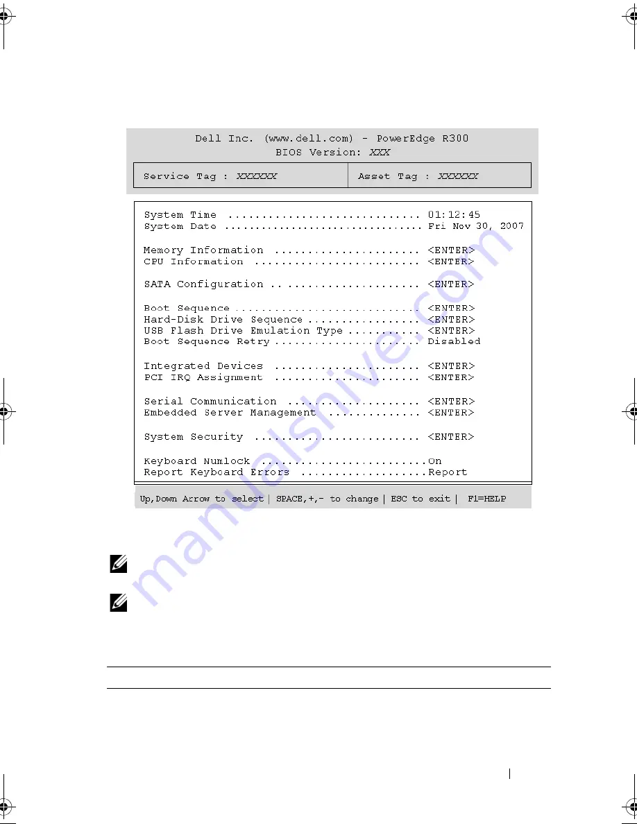
Figure 2-1.
Main System Setup Program Screen
Table 2-2 lists the options and descriptions for the information fields that
appear on the main System Setup program screen.
NOTE:
The options for the System Setup program change based on the system
configuration.
NOTE:
The System Setup program defaults are listed under their respective
options, where applicable.
Table 2-2.
System Setup Program Options
Option
Description
System Time
Sets the time on the system's internal clock.
System Date
Sets the date on the system's internal calendar.
book.book Page 49 Sunday, June 21, 2009 5:16 PM
Summary of Contents for PowerEdge R300
Page 10: ...10 Contents ...
Page 46: ...46 About Your System ...
Page 64: ...64 Using the System Setup Program ...
Page 166: ...166 Jumpers and Connectors ...
Page 168: ...168 Getting Help ...
Page 186: ...186 Index W warning messages 44 warranty 11 wet system troubleshooting 132 ...


