background image

Installing System Components

67

4

Remove the heat sink, see "Removing the Heat Sink" on page 64.


CAUTION: 

The processor is held in its socket under strong pressure. Be aware 

that the release lever can spring up suddenly if not firmly grasped.

5

Position your thumb firmly over the processor socket-release lever and 
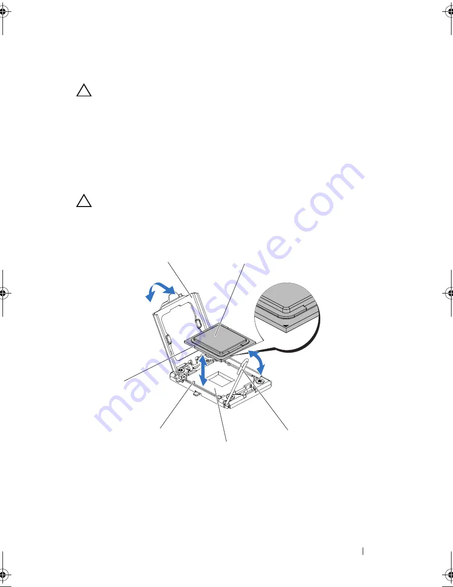
release the lever from the locked position. Rotate the lever 90 degrees 
upward until the processor is released from the socket. See Figure 3-9.

6

Rotate the processor shield upward and out of the way. See Figure 3-9.

7

Lift the processor out of the socket and leave the socket-release lever up so 
that the socket is ready for the new processor


CAUTION: 

Be careful not to bend any of the pins on the ZIF socket when removing 

the processor. Bending the pins can permanently damage the system board.

Figure 3-9.

Removing and Installing a Processor

1

processor shield 

2

processor 

3

socket-release lever 

4

ZIF socket

5

socket key (2) 

6

notch in processor (2)

2

1

6

3

4

5

book.book  Page 67  Thursday, March 4, 2010  4:38 PM

Summary of Contents for PowerEdge C6100

Page 1: ...Dell PowerEdge C6100 Systems Hardware Owner s Manual Regulatory Model XS23 TY3 ...

Page 2: ... these materials in any manner whatsoever without the written permission of Dell Inc is strictly forbidden Trademarks used in this text Dell the DELL logo and PowerEdge are trademarks of Dell Inc Intel is a registered trademark of Intel Corporation in the U S and other countries Red Hat is a registered trademark of Red Hat Inc in the United States and other countries Other trademarks and trade nam...

Page 3: ...res and Indicators 16 NIC Indicator Codes 18 Power and System Board Indicator Codes 20 Power Supply Indicator Codes 21 BMC Heart Beat LED 22 POST Error Codes 23 Collecting System Event Log for Investigation 23 Other Information You May Need 33 2 Using the System Setup Program 35 Start Menu 35 System Setup Options at Boot 36 Console Redirection 36 Main Menu 37 Main Screen 37 ...

Page 4: ...ation 43 PCI Configuration 44 Boot Menu 45 Boot Settings Configuration 45 Security Menu 45 Server Menu 47 System Management 48 Remote Access Configuration 48 IPMI Configuration 49 LAN Configuration 50 Power Throttling Configuration 50 IP Address 50 Subnet Mask 51 Default Gateway IP 51 Exit Menu 51 3 Installing System Components 53 Safety Instructions 53 Recommended Tools 53 Inside the System 54 ...

Page 5: ...lling a Power Supply 60 System Board Assembly 61 Removing a System Board Assembly 61 Installing a System Board Assembly 62 Cooling Shroud 63 Removing the Cooling Shroud 63 Installing the Cooling Shroud 64 Heat Sinks 64 Removing the Heat Sink 64 Installing the Heat Sink 66 Processor 66 Removing a Processor 66 Installing a Processor 68 Expansion Card Assembly and Expansion Card 69 Removing the Expan...

Page 6: ...Memory Modules 80 Interposer Extenders 82 Removing the Interposer Extender 82 Installing the Interposer Extender 83 System Battery 84 Replacing the System Battery 84 RAID Battery Optional 85 Removing the RAID Battery 85 Installing the RAID Battery 86 Removing the RAID Battery Carrier 87 Installing the RAID Battery Carrier 88 System Board 89 Removing a System Board 89 Installing a System Board 90 O...

Page 7: ...es 104 Backplanes 105 Removing the Backplane 105 Installing the Backplane 108 Front Panels 109 Removing the Front Panel 109 Installing Front Panel 111 4 Troubleshooting Your System 113 Safety First For You and Your System 113 Installation Problems 113 Troubleshooting System Startup Failure 114 Troubleshooting External Connections 114 Troubleshooting the Video Subsystem 114 Troubleshooting a USB De...

Page 8: ...shooting System Memory 121 Troubleshooting a Hard Drive 123 Troubleshooting a Storage Controller 124 Troubleshooting Expansion Cards 125 Troubleshooting Processors 126 IRQ Assignment Conflicts 127 5 Jumpers and Connectors 129 System Board Connectors 129 Backplane Connectors 130 3 5 drives 130 2 5 drives 132 Midplane Connectors 134 Interposer Extender Connectors 135 Mezzanine Card Connectors 136 Fa...

Page 9: ...ontents 9 Power Distribution Board Connectors 139 Jumper Settings 139 System Configuration Jumper Settings 140 Backplane Jumper Settings 141 6 Getting Help 143 Contacting Dell 143 Glossary 145 Index 155 ...

Page 10: ...10 Contents ...

Page 11: ...BIOS Boot Manager See System Setup Options at Boot on page 36 F12 Starts Preboot eXecution Environment PXE boot Ctrl C Enters the SAS Configuration Utility For more information see the SAS adapter documentation Ctrl H Enters the RAID configuration utility For more information see the documentation for your SAS RAID card Ctrl S Enters the utility to configure NIC settings for PXE boot For more info...

Page 12: ...igure 1 2 Front Panel 3 5 Hard Drives With Three System Boards Figure 1 3 Front Panel 3 5 Hard Drives With Two System Boards 1 0 1 1 1 2 2 0 2 1 2 2 3 0 3 1 3 2 4 0 4 1 4 2 1 2 3 4 6 7 8 9 5 1 0 2 0 4 0 1 1 2 1 4 1 1 2 2 2 4 2 1 3 2 3 4 3 1 2 3 4 5 6 7 8 9 2 0 2 1 2 2 2 3 2 4 2 5 4 0 4 1 4 2 4 3 4 4 4 5 1 2 3 4 5 6 7 8 9 ...

Page 13: ...ure 1 5 Front Panel 2 5 Hard Drives With Three System Boards 1 0 1 1 1 2 1 3 1 4 1 5 2 0 2 1 2 2 2 3 2 4 2 5 3 0 3 1 3 2 3 3 3 4 3 5 4 0 4 1 4 2 4 3 4 4 4 5 1 2 3 4 5 6 7 8 9 1 0 1 1 1 2 1 3 1 4 1 5 1 6 1 7 2 0 2 1 2 2 2 3 2 4 2 5 2 6 2 7 4 0 4 1 4 2 4 3 4 4 4 5 4 6 4 7 1 3 4 5 2 7 9 8 6 ...

Page 14: ...in the system NOTE On ACPI compliant operating systems turning off the system using the power button causes the system to perform a graceful shutdown before power to the system is turned off NOTE To force an ungraceful shutdown press and hold the power button for 5 seconds 2 4 6 8 System identification indicator button system boards 1 2 4 3 The identification button can be used to locate a particu...

Page 15: ...es Drive cover Applicable only for 2 5 hard drive system 1 hard drive activity indicator green 2 hard drive status indicator green and amber Drive Status Indicator Pattern Condition Off Slot empty Solid green Hard drive online access Blinks green Hard drive rebuilding hard drive identification preparing for removal Blinks green amber Rebuild abort Blinks amber Hard drive failed Item Indicator Butt...

Page 16: ...ant 4 System identification indicator Both the systems management software and the identification buttons located on the front can cause the indicator to flash blue to identify a particular system and system board Lights amber when the system needs attention due to a problem 5 Ethernet connector 1 Embedded 10 100 1000 NIC connectors 6 Ethernet connector 2 Embedded 10 100 1000 NIC connectors 7 KVM ...

Page 17: ...ut to the system NOTE When powering on the system the video monitor can take from several seconds to over 2 minutes to display an image depending on the amount of memory installed in the system NOTE On ACPI compliant operating systems turning off the system using the power button causes the system to perform a graceful shutdown before power to the system is turned off NOTE To force an ungraceful s...

Page 18: ...icators 1 link indicator 2 activity indicator NIC Status Indicator link Condition Steady amber Link at 1 Gbps speed Blinks amber Identifying port with 1 Gbps connection Steady green Link at 100 Mbps speed Blinks green Identifying port with 10 Mbps or 100 Mbps connection Off Link at 10 Mbps speed 4 2 1 2 ...

Page 19: ... green Link LAN No access Blinks green Accessing LAN Off Idle 1 link indicator 2 activity indicator NIC Status Indicator link Condition Steady Green Link at 100 Mbps speed Off Link at 10 Mbps speed NIC Status Indicator activity Condition Steady green Link LAN No access Blinks green LAN access Green off Idle 1 2 ...

Page 20: ...1 2 lists the status associated with the status codes Table 1 2 Status Indicator Codes Component Indicator Condition Power on indicator Steady Green Blinks Amber Blinks Green Amber Power On S0 S1 BMC Critical condition event in Power Off mode S4 S5 BMC Critical condition event in Power On mode S0 S1 System identification indicator Steady Blue Blinks Blue Off IPMI Via Chassis Identify Command On or...

Page 21: ...2 power supply indicator Power Supply Status Indicator Condition Steady green Power supply is on AC OK DC OK or in standby mode 90 VAC 264 VAC Steady yellow Power supply faulty UVP OVP OCP SCP OTP Fan Fault Yellow off Power supply is off or AC input voltage is out of normal operating range 90 VAC 264 VAC 1 2 ...

Page 22: ...ystem BMC Heart Beat LED The system board provides BMC heart beat LED CR24 for BMC debugs When BMC firmware is ready the BMC heart beat LED blinks Figure 1 15 BMC Heart Beat LED 1 BMC heart beat LED 2 system board 2 1 ...

Page 23: ...estart the system If the problem persists see Getting Help on page 143 0003h Yes CMOS Battery Error See Troubleshooting the System Battery on page 118 0004h Yes CMOS Diagnostic Status Error Remove AC power to the system for 10 seconds and restart the system If the problem persists see Getting Help on page 143 0005h Yes CMOS Checksum Error Remove AC power to the system for 10 seconds and restart th...

Page 24: ...sts see Getting Help on page 143 0041h Yes Display Memory Error Remove AC power to the system for 10 seconds and restart the system If the problem persists see Getting Help on page 143 0044h Yes DMAC Controller Error See Troubleshooting System Memory on page 121 If the problem persists see Getting Help on page 143 0045h Yes DMAC1 Channel Register Error See Troubleshooting System Memory on page 121...

Page 25: ...eature Error See Getting Help on page 143 005Eh Yes Non Critical Password Check Error Reset password See Jumper Settings on page 139 If the problem persists see Getting Help on page 143 0060h Yes HDD 0 Error See Troubleshooting a Hard Drive on page 123 0061h Yes HDD 1 Error See Troubleshooting a Hard Drive on page 123 0062h Yes HDD 2 Error See Troubleshooting a Hard Drive on page 123 0063h Yes HDD...

Page 26: ...system for 10 seconds and restart the system If the problem persists see Getting Help on page 143 0083h Yes ATAPI 3 Error Remove AC power to the system for 10 seconds and restart the system If the problem persists see Getting Help on page 143 0084h Yes ATAPI 4 Error Remove AC power to the system for 10 seconds and restart the system If the problem persists see Getting Help on page 143 0085h Yes AT...

Page 27: ... heat sinks are properly installed See Troubleshooting Processors on page 126 and Troubleshooting System Cooling Problems on page 120 0121h Yes CPU2 Thermal Failure due to PROCHOT Ensure that the processor heat sinks are properly installed See Troubleshooting Processors on page 126 and Troubleshooting System Cooling Problems on page 120 0122h Yes CPU3 Thermal Failure due to PROCHOT Ensure that the...

Page 28: ...restart the system If the problem persists see Getting Help on page 143 0152h Yes Processor failed BIST Remove AC power to the system for 10 seconds and restart the system If the problem persists see Getting Help on page 143 0153h Yes Processor failed BIST Remove AC power to the system for 10 seconds and restart the system If the problem persists see Getting Help on page 143 0160h Yes CPU1 Process...

Page 29: ...tting Started Guide 0181 Yes CPU 2 stepping no support Ensure that your processors match and conform to the type described in the processor technical specifications outlined in your system s Getting Started Guide 0182 Yes CPU 3 stepping no support Ensure that your processors match and conform to the type described in the processor technical specifications outlined in your system s Getting Started ...

Page 30: ...ping are different Ensure that your processors match and conform to the type described in the processor technical specifications outlined in your system s Getting Started Guide 0195h Yes Front side bus mismatch Ensure that your processors match and conform to the type described in the processor technical specifications outlined in your system s Getting Started Guide 0196h Yes CPUID Processor Model...

Page 31: ...ing Help on page 143 8102h No USB Device Init Error See Troubleshooting a USB Device on page 114 If the problem persists see Getting Help on page 143 8103h No USB Device Disabled To enable USB device see USB Configuration on page 43 See Troubleshooting a USB Device on page 114 If the problem persists see Getting Help on page 143 8104h No USB OHCI EMUL Not Supported See Troubleshooting a USB Device...

Page 32: ...on page 143 F001h No System Event Log Full Check the SEL for details on the events then clear the SEL F002h No BMC FRU Header checksum bad Remove AC power to the system for 10 seconds and restart the system If the problem persists see Getting Help on page 143 F003h No BIOS Update BMC FRU failed Remove AC power to the system for 10 seconds and restart the system If the problem persists see Getting ...

Page 33: ...nical specifications NOTE Always check for updates on support dell com manuals and read the updates first because they often supersede information in other documents F005h No BIOS Update FRU Internal Area checksum failed Remove AC power to the system for 10 seconds and restart the system If the problem persists see Getting Help on page 143 FFFFh No Undefined BIOS Error Remove AC power to the syste...

Page 34: ...34 About Your System ...

Page 35: ...onboard write protected DRAM This Setup utility should be executed under the following conditions When changing the system configuration configure items such as Hard drives diskette drives and peripherals Password protection from unauthorized use Power management features When a configuration error is detected by the system and you are prompted to make changes to the Setup utility When redefining ...

Page 36: ...nsole redirection is the BIOS Console The BIOS Console is a Flash ROM resident utility that redirects input and output over a serial or modem connection The BIOS supports console redirection to a serial port If serial port based headless system support is provided by the system the system must provide support for redirection of all BIOS driven console I O to the serial port The driver for the seri...

Page 37: ... options for the System Setup program change based on the system configuration NOTE The System Setup program defaults are listed under their respective options in the following sections where applicable Use ENTER TAB or SHIFT TAB to select a field Use or to configure system Time Select Screen Select Item Tab F1 F10 Save and Exit ESC Change Field Select Field General Help Exit ...

Page 38: ...ays the date the BIOS was created ID Displays the BIOS ID Option Description Type Displays the type of processor installed on the system board Speed Displays the maximum speed of the processor Count Displays the number of installed processors Option Description Size Displays how much memory DRAM is installed on the system board System Time Scroll to this item to adjust the time System Date Scroll ...

Page 39: ...abled default Enable this option when the processor supports VT A full reset is needed to change its state Execute Disable Bit Capability Enabled default Forces the XD feature flag to always return 0 C1E Support Enabled default Enable this option to enable or disable the Enhanced Halt State Hardware Prefetcher Enabled default For UP Platforms leave it enabled For DP MP servers it may used to tune ...

Page 40: ...idle is set to C2 C3 C4 C6 State Enabled default C6 Support When CPU is in idle mode Option Description Memory Frequency Auto default Forces a DDR3 frequency slower than the common tck detected using SPD Memory Mode Independent default Independent independent channel NUMA Support Enabled default Enables or disables NUMA Enabled efficiently executes software for NUMA aware operating system Disabled...

Page 41: ...Port 1 3 AHCI RAID AHCI Port 0 5 Hard Disk Write Protect Disabled default Enables or disables device write protection This is effective only if the device is accessed through BIOS IDE Detect Time Out Sec 35 default Selects the time out value for detecting ATA ATAPI device s Option Description Device Displays the type of device assigned to this channel Vendor Displays the manufacturer s name of the...

Page 42: ...d LAB access mode is disabled Auto Enables LAB Mode if the device supports it and the device is not already formatted with LAB mode disabled Block Multi Sector Transfer Auto default Enables multi sector transfer block mode Disabled data transfer from and to the device occurs one sector at a time Auto data transfer from and to the device occurs multiple sectors at a time if supported by the device ...

Page 43: ...yte of transfer Auto automatically detects optimal or default DMA mode SWDMA0 SWDMA2 selects SingleWord DMA 0 to 2 MWDMA0 MWDMA2 selects MultiWord DMA 0 to 2 UDMA 0 UDMA5 selects Ultra DMA 0 to 5 S M A R T Auto default Self Monitoring Analysis and Reporting Technology reports drive degradation to the operating system to warn you of potential failure Auto automatically sets optimal or default S M A...

Page 44: ...e POST waits for the USB mass storage device after the start Unit command is issued Device USB device model name Emulation Type Auto default If Auto USB devices which are less than 530 MB are emulated as floppy and others are be emulated as hard disk Forced FDD option can be used to force a formatted hard drive to boot as FDD e g ZIP drive Option Description NIC Function Support PXE default NIC Fu...

Page 45: ...es CD DVD Drives Specifies the boot device priority sequence from the available CD DVD drives Option Description Quick Boot Enabled default Allows BIOS to skip certain tests during the POST which decreases boot up time Quiet Boot Disabled default Enables or disables this item Disabled displays normal POST messages Enabled displays OEM logo instead of POST messages Wait For F1 If Error Disabled def...

Page 46: ...er Access Level Full Access default Sets the user access level No Access prevents user access to the Setup Utility View Only allows user access to the Setup Utility but the fields cannot be changed Limited allows only limited fields to be changed such as date and time Full Access allows user access to the Setup Utility and the fields can be changed Change User Password Installs changes or clears t...

Page 47: ...is disabled If OS Control EIST or Node Management is selected Intel SpeedStep is enabled ME function is disabled if OS Control EIST is selected IOAT2 Disabled default Enables or disables IOAT2 Wake on RING function Disabled default Enables or disables Wake on RING function WHEA Support Disabled default Enables or disables Windows Hardware Error Architecture Restore on AC Power Loss Power On defaul...

Page 48: ...hassis serial numbers BIOS Version Displays current BIOS version BMC Device ID Displays BMC device ID BMC Firmware Revision Displays BMC firmware version FCB Firmware Revision Displays FCB firmware version Option Description Remote Access Enabled default Selects remote access type Serial Port Number COM1 default Selects serial port for console redirection Make sure the selected port is enabled Thi...

Page 49: ... Always redirection is always active Some operating systems may not work if set to Always Terminal Type VT100 default Selects the target terminal type This item disappears when Remote Access is disabled VT UTF8 Combo Key Support Enabled default Enables or disables VT UTF8 combination key support for ANSI VT100 terminals This item disappears when Remote Access is disabled Terminal Display Mode Norm...

Page 50: ...ption Description Channel Number 01 default Enters channel number for SET LAN Config Command Proper value is below 16 BMC IP address source DHCP default Sets BMC IP address source from BIOS Option Description Power Throttling Enable or disable Power throttling Power CAP Enable or disable Power CAP Chassis CAP Set Chassis CAP value Option Description IP Address default value depends on BMC setting ...

Page 51: ...n Description Save Changes and Exit Select this item and press Enter to save any changes that you have made in the Setup utility and exit the Setup utility When the Save Changes and Exit dialog box appears Select OK to save the changes and exit or press N to return to the setup main menu Discard Changes and Exit Select this item and press Enter to discard any changes that you have made in the Setu...

Page 52: ...ly if you are using slower memory chips or other kinds of low performance components Load Failsafe Defaults If you select this item and press Enter a dialog box asks if you want to install fail safe settings for all the items in the Setup utility Select OK to indicate Yes and then press Enter to install the fail safe settings The fail safe settings default values are not demanding so a system shou...

Page 53: ...w the safety instructions that came with the product To avoid injury to yourself or damage to your system follow these guidelines Always disconnect the system from the power outlet whenever you are working inside the system If possible wear a grounded wrist strap when you are working inside the system Alternatively discharge any static electricity by touching the bare metal chassis of the system c...

Page 54: ...am Damage due to servicing that is not authorized by Dell is not covered by your warranty Read and follow the safety instructions that came with the product CAUTION This system must be operated with the system cover installed to ensure proper cooling NOTE The illustration in this section shows a system with 3 5 inch hard drives Figure 3 1 Inside the System 1 system board assembly 4 2 power supply ...

Page 55: ...all empty hard drive bays must have drive blanks installed NOTE This section is applicable to systems with hot swappable hard drives only 1 Grasp the front of the hard drive blank pull and slide the blank out until it is free of the drive bay See Figure 3 2 Figure 3 2 Removing or Installing a Hard Drive Blank Installing a Hard Drive Blank Align the hard drive blank with the drive bay and insert th...

Page 56: ...l is not covered by your warranty Read and follow the safety instructions that came with the product 1 Turn the lock lever counterclockwise until it points to the unlock symbol 2 Slide the release button to open the release handle See Figure 3 3 3 Using the release handle pull the hard drive carrier out of the hard drive bay CAUTION To maintain proper system cooling all empty hard drive bays must ...

Page 57: ...ice technician You should only perform troubleshooting and simple repairs as authorized in your product documentation or as directed by the online or telephone service and support team Damage due to servicing that is not authorized by Dell is not covered by your warranty Read and follow the safety instructions that came with the product CAUTION Combining SATA and SAS hard drives in the same system...

Page 58: ...imple repairs as authorized in your product documentation or as directed by the online or telephone service and support team Damage due to servicing that is not authorized by Dell is not covered by your warranty Read and follow the safety instructions that came with the product 1 Place the hard drive into the hard drive carrier See Figure 3 4 2 Secure the hard drive to the hard drive carrier with ...

Page 59: ...s one power supply to operate normally 1 Turn off the system including any attached peripherals and disconnect the system from the electrical outlet 2 Disconnect the power cable from the power source and the power supply Table 3 1 PSU and System Board Support Matrix PSU Two System Boards Three System Boards Four System Boards 1400 W Full configuration Full configuration Up to two processors twelve...

Page 60: ...entation or as directed by the online or telephone service and support team Damage due to servicing that is not authorized by Dell is not covered by your warranty Read and follow the safety instructions that came with the product CAUTION The system requires one power supply to operate normally 1 Verify that both power supplies are of the same type and have the same maximum output power NOTE The ma...

Page 61: ...eshooting and simple repairs as authorized in your product documentation or as directed by the online or telephone service and support team Damage due to servicing that is not authorized by Dell is not covered by your warranty Read and follow the safety instructions that came with the product 1 Turn off the system including any attached peripherals and disconnect the system from its electrical out...

Page 62: ...d support team Damage due to servicing that is not authorized by Dell is not covered by your warranty Read and follow the safety instructions that came with the product 1 Slide the system board assembly into the chassis until it snaps into place See Figure 3 6 2 Reconnect all the external cables to the system board 3 Replace the screw that secures the retaining latch See Figure 3 6 4 Reconnect the...

Page 63: ...t authorized by Dell is not covered by your warranty Read and follow the safety instructions that came with the product 1 Turn off the system including any attached peripherals and disconnect the system from its electrical outlet 2 Remove the system board assembly See Removing a System Board Assembly on page 61 3 Push out one side of the cooling shroud in the direction of the arrow See Figure 3 7 ...

Page 64: ... CAUTION Many repairs may only be done by a certified service technician You should only perform troubleshooting and simple repairs as authorized in your product documentation or as directed by the online or telephone service and support team Damage due to servicing that is not authorized by Dell is not covered by your warranty Read and follow the safety instructions that came with the product 1 T...

Page 65: ...igure 3 8 Wait for 30 seconds for the heat sink to loosen from the processor 5 Remove the other three heat sink retention screws 6 Gently lift the heat sink off the processor and set the heat sink aside with thermal grease side facing up Figure 3 8 Removing and Installing the Heat Sink 1 screw 4 2 heat sink 1 1 2 ...

Page 66: ...illips screwdriver tighten the four heat sink retention screws 5 Replace the cooling shroud see Removing the Cooling Shroud on page 63 6 Replace the system board assembly See Installing a System Board Assembly on page 62 7 Reconnect the system to its electrical outlet and turn on the system including any attached peripherals Processor Removing a Processor CAUTION Many repairs may only be done by a...

Page 67: ...upward until the processor is released from the socket See Figure 3 9 6 Rotate the processor shield upward and out of the way See Figure 3 9 7 Lift the processor out of the socket and leave the socket release lever up so that the socket is ready for the new processor CAUTION Be careful not to bend any of the pins on the ZIF socket when removing the processor Bending the pins can permanently damage...

Page 68: ... been used remove any thermal grease from the top of the processor using a lint free cloth 2 Align the processor with the socket keys on the ZIF socket See Figure 3 9 CAUTION Positioning the processor incorrectly can permanently damage the system board or the processor Be careful not to bend the pins in the ZIF socket 3 With the release lever on the processor socket in the open position align the ...

Page 69: ...a certified service technician You should only perform troubleshooting and simple repairs as authorized in your product documentation or as directed by the online or telephone service and support team Damage due to servicing that is not authorized by Dell is not covered by your warranty Read and follow the safety instructions that came with the product 1 Turn off the system including any attached ...

Page 70: ...oving the Expansion Card Assembly 6 Remove the screw securing the expansion card Figure 3 11 Removing the Expansion Card 1 screw 5 2 expansion card assembly 1 expansion card slot cover 2 screw 3 expansion card 4 expansion card connector 1 2 4 1 2 3 ...

Page 71: ...by the online or telephone service and support team Damage due to servicing that is not authorized by Dell is not covered by your warranty Read and follow the safety instructions that came with the product CAUTION Expansion cards can only be installed in the slots on the expansion card riser Do not attempt to install expansion cards directly into the riser connector on the system board 1 Unpack th...

Page 72: ...embly 13 Replace the five screws that secure the expansion card assembly 14 Replace the cooling shroud See Installing the Cooling Shroud on page 64 15 Replace the system board assembly See Installing a System Board Assembly on page 62 16 Reconnect the system to its electrical outlet and turn on the system including any attached peripherals Expansion Card Connector Removing the Expansion Card Conne...

Page 73: ... two screws securing the expansion card connector to the expansion card bracket See Figure 3 12 5 Pull the expansion card connector away from the expansion card bracket See Figure 3 12 Figure 3 12 Removing and Installing the Expansion Card Connector 1 screw 2 2 expansion card connector 3 expansion card bracket 3 2 1 ...

Page 74: ...lling a System Board Assembly on page 62 5 Reconnect the system to its electrical outlet and turn on the system including any attached peripherals Mezzanine Card Removing the SAS Mezzanine Card CAUTION Many repairs may only be done by a certified service technician You should only perform troubleshooting and simple repairs as authorized in your product documentation or as directed by the online or...

Page 75: ...e to servicing that is not authorized by Dell is not covered by your warranty Read and follow the safety instructions that came with the product 1 Place the mezzanine card on the system board assembly See Figure 3 13 and Figure 5 11 2 Replace the three screws that secure the mezzanine card See Figure 3 13 3 Reconnect all the cables to the mezzanine card 4 Replace the system board assembly See Inst...

Page 76: ...the product 1 Turn off the system including any attached peripherals and disconnect the system from its electrical outlet 2 Disconnect all the cables from the mezzanine card 3 Remove the system board assembly See Removing a System Board Assembly on page 61 4 Remove the three screws that secure the mezzanine card to the back of system board tray See Figure 3 14 5 Remove the screw that secures the m...

Page 77: ...stem board tray See Figure 3 14 3 Replace the screw that secures the mezzanine card side bracket to the system board tray See Figure 3 14 4 Replace the system board assembly See Installing a System Board Assembly on page 62 5 Reconnect all the cables to the mezzanine card 6 Reconnect the system to its electrical outlet and turn on the system including any attached peripherals System Memory Each sy...

Page 78: ...CHC 2 DIMM1_CHC 3 DIMM0_CHB 4 DIMM1_CHB 5 DIMM0_CHA 6 DIMM1_CHA 7 DIMM1_CHA 8 DIMM0_CHA 9 DIMM1_CHB 10 DIMM0_CHB 11 DIMM1_CHC 12 DIMM0_CHC Table 3 2 Memory Module Configurations DIMM DIMM0 DIMM1 DIMM0 DIMM1 DIMM0 DIMM1 Processor 0 CH A CH B CH C 1 4 1 2 3 4 5 6 12 11 10 9 8 7 ...

Page 79: ... should only perform troubleshooting and simple repairs as authorized in your product documentation or as directed by the online or telephone service and support team Damage due to servicing that is not authorized by Dell is not covered by your warranty Read and follow the safety instructions that came with the product 1 Turn off the system including any attached peripherals and disconnect the sys...

Page 80: ...onents on the memory module CAUTION Many repairs may only be done by a certified service technician You should only perform troubleshooting and simple repairs as authorized in your product documentation or as directed by the online or telephone service and support team Damage due to servicing that is not authorized by Dell is not covered by your warranty Read and follow the safety instructions tha...

Page 81: ...o lock the memory module into the socket See Figure 3 16 When the memory module is properly seated in the socket the ejectors on the memory module socket align with the ejectors on the other sockets that have memory modules installed 9 Repeat step 5 through step 8 of this procedure to install the remaining memory modules in the approved configurations See Table 3 2 10 Replace the cooling shroud Se...

Page 82: ...ubleshooting and simple repairs as authorized in your product documentation or as directed by the online or telephone service and support team Damage due to servicing that is not authorized by Dell is not covered by your warranty Read and follow the safety instructions that came with the product Removing the Interposer Extender 1 Turn off the system including any attached peripherals and disconnec...

Page 83: ...ot authorized by Dell is not covered by your warranty Read and follow the safety instructions that came with the product 1 Place the interposer extender into the interposer extender tray 2 Replace the five screws that secure the interposer extender to the interposer extender tray 3 Connect all the cables to the interposer extender See Figure 5 9 4 Replace the system board assembly See Installing a...

Page 84: ...ple repairs as authorized in your product documentation or as directed by the online or telephone service and support team Damage due to servicing that is not authorized by Dell is not covered by your warranty Read and follow the safety instructions that came with the product 1 Turn off the system including any attached peripherals and disconnect the system from the electrical outlet 2 Remove the ...

Page 85: ...ding any attached peripherals 9 Enter the System Setup program to confirm that the battery is operating properly See Using the System Setup Program on page 35 10 Enter the correct time and date in the System Setup program s Time and Date fields 11 Exit the System Setup program RAID Battery Optional Removing the RAID Battery CAUTION Many repairs may only be done by a certified service technician Yo...

Page 86: ...release it from the RAID battery carrier See Figure 3 19 5 Slide and lift the RAID battery away from the RAID battery carrier See Figure 3 19 Figure 3 19 Removing and Installing the RAID Battery Installing the RAID Battery 1 Insert the RAID battery into the battery carrier until the RAID battery latch locks into place See Figure 3 19 2 Connect the RAID battery cable to the connector on the PERC ca...

Page 87: ...l is not covered by your warranty Read and follow the safety instructions that came with the product NOTE The information in this section applies only to systems with the optional RAID controller card 1 Turn off the system including any attached peripherals and disconnect the system from the electrical outlet 2 Remove the system board assembly See Removing a System Board Assembly on page 61 3 Remo...

Page 88: ...ews securing the RAID battery carrier to the interposer extender See Figure 3 20 3 Install the RAID battery into the RAID battery carrier See Installing the RAID Battery on page 86 4 Replace the system board assembly See Installing a System Board Assembly on page 62 5 Reconnect the system to the electrical outlet and turn the system on including any attached peripherals 1 RAID battery carrier 2 sc...

Page 89: ...embly See Removing a System Board Assembly on page 61 3 Remove the cooling shroud See Removing the Cooling Shroud on page 63 4 Remove the heat sink See Removing the Heat Sink on page 64 5 Remove the expansion card assembly See Removing the Expansion Card on page 69 6 If installed remove the SAS mezzanine card or the Inifniband mezzanine card See Removing the SAS Mezzanine Card on page 74 or Removi...

Page 90: ...cure the system board to the system board assembly 4 Transfer the processors to the new system board See Removing a Processor on page 66 and Installing a Processor on page 68 5 Remove the memory modules and transfer them to the same locations on the new board See Interposer Extenders on page 82 and Installing Memory Modules on page 80 6 Replace the cooling shroud see Installing the Cooling Shroud ...

Page 91: ... the system by yourself CAUTION This system must be operated with the system cover installed to ensure proper cooling CAUTION Many repairs may only be done by a certified service technician You should only perform troubleshooting and simple repairs as authorized in your product documentation or as directed by the online or telephone service and support team Damage due to servicing that is not auth...

Page 92: ...cure the cover with the securing screw See Figure 3 22 Cooling Fans Removing a Cooling Fan WARNING Do not attempt to operate the system without the cooling fans WARNING The cooling fan can continue to spin for some time after the system has been powered down Allow time for the fan to stop spinning before removing it from the system 1 traction pad 2 system cover 3 cover release latch lock 4 securin...

Page 93: ...ns that came with the product 1 Turn off the system including any attached peripherals and disconnect the system from its electrical outlet 2 Open the system See Opening the System on page 91 3 Disconnect the fan s power cable from the fan controller board Note the routing of the cable underneath the tabs on the chassis as you remove them from the system You must route these cables properly when y...

Page 94: ...g the System on page 92 4 Reconnect the system to its electrical outlet and turn on the system including any attached peripherals Power Distribution Boards Removing a Power Distribution Board CAUTION Many repairs may only be done by a certified service technician You should only perform troubleshooting and simple repairs as authorized in your product documentation or as directed by the online or t...

Page 95: ...move the screws securing the first power distribution board to the system See Figure 3 24 6 Lift the power distribution board out of the system See Figure 3 24 NOTE To remove the second power distribution board that is below the first power distribution board remove the power distribution board connector and angle the board before lifting Figure 3 24 Removing and Installing a Power Distribution Bo...

Page 96: ...place the second power distribution board in the system See Figure 3 24 Otherwise skip to step 5 NOTE To install the second power distribution board that is below the first power distribution board angle the board during installation 2 Replace the screws securing the second power distribution board to the system See Figure 3 24 3 Replace the power distribution board connector See Figure 3 24 4 Con...

Page 97: ...by Dell is not covered by your warranty Read and follow the safety instructions that came with the product 1 Turn off the system including any attached peripherals and disconnect the system from its electrical outlet 2 Open the system See Opening the System on page 91 3 Remove the power distribution boards See Removing a Power Distribution Board on page 94 4 Disconnect all the cables from the fan ...

Page 98: ...upport team Damage due to servicing that is not authorized by Dell is not covered by your warranty Read and follow the safety instructions that came with the product 1 Place the fan controller board into the chassis and slide it into place See Figure 3 25 2 Replace the screw to secure the fan controller board to the chassis See Figure 3 25 3 Connect all the cables to the fan controller board See F...

Page 99: ...ation or as directed by the online or telephone service and support team Damage due to servicing that is not authorized by Dell is not covered by your warranty Read and follow the safety instructions that came with the product 1 Turn off the system including any attached peripherals and disconnect the system from its electrical outlet 2 Open the system See Opening the System on page 91 3 Remove th...

Page 100: ...connect all the cables from the upper midplane See Figure 5 9 Note the routing of the cable underneath the tabs on the chassis as you remove them from the system You must route these cables properly when you replace them to prevent the cables from being pinched or crimped 9 Lift the upper midplane out Figure 3 27 1 cooling fan bracket long 2 screw 14 3 cooling fan bracket short 1 3 2 ...

Page 101: ... 3 27 Removing and Installing the Upper Midplane 10 Remove the screws that secure the mid plane holder support to the chassis See Figure 3 28 11 Lift the mid plane holder support out of the chassis Figure 3 28 1 screw 9 2 upper midplane 1 2 ...

Page 102: ... 28 Removing and Installing the Mid Plane Holder Support 12 Remove the screws that secure the mid plane holder to the chassis Figure 3 29 13 Lift the mid plane holder out of the chassis See Figure 3 29 1 screw 4 2 mid plane holder support 1 2 ...

Page 103: ...5 Disconnect all the cables from the lower midplane See Figure 5 9 Note the routing of the cable underneath the tabs on the chassis as you remove them from the system You must route these cables properly when you replace them to prevent the cables from being pinched or crimped 16 Lift the lower midplane out of the chassis See Figure 3 30 1 screw 8 2 mid plane holder 1 2 ...

Page 104: ...ranty Read and follow the safety instructions that came with the product 1 Place the lower midplane into the chassis See Figure 3 30 2 Replace the screws that secure the lower midplane to the chassis See Figure 3 30 3 Connect all the cables to the lower midplane See Figure 5 9 You must route these cables properly through the tabs on the chassis to prevent them from being pinched or crimped 4 Place...

Page 105: ...sing the System on page 92 16 Reconnect the system to its electrical outlet and turn on the system including any attached peripherals Backplanes NOTE Following is the replacement procedure of SATA2 and SAS backplane for 3 5 inch hard drive systems Replacement procedure for 2 5 inch of SATA2 and SAS backplane is similar to backplane for 3 5 inch hard drive systems Removing the Backplane CAUTION Man...

Page 106: ...rews that secure the hard drive cage to the chassis See Figure 3 31 Figure 3 31 Removing and Installing the Backplane 5 Remove the screws that secure the front panel assemblies to the chassis See Figure 3 32 6 Disconnect all the cables from the backplane See Figure 5 3 for 3 5 inch hard drives and Figure 5 6 for 2 5 inch hard drives Note the routing of the cable underneath the tabs on the chassis ...

Page 107: ...st route these cables properly when you replace them to prevent the cables from being pinched or crimped 8 Remove the hard drive cage from the chassis See Figure 3 32 Figure 3 32 Removing and Installing the Hard Drive Cage 9 Remove the screws that secure the backplane to the hard drive cage See Figure 3 33 10 Remove the backplane from the hard drive cage See Figure 3 33 1 hard drive cage 2 front p...

Page 108: ...nty Read and follow the safety instructions that came with the product 1 Install the backplane into the hard drive cage See Figure 3 33 2 Replace the screws that secure the backplane to the hard drive cage See Figure 3 33 3 Replace the hard drive cage into the chassis See Figure 3 32 4 Replace the screws that secure the front panel assemblies to the chassis See Figure 3 32 5 Connect all the cables...

Page 109: ...am Damage due to servicing that is not authorized by Dell is not covered by your warranty Read and follow the safety instructions that came with the product 1 Turn off the system including any attached peripherals and disconnect the system from the electrical outlet 2 Remove all the hard drives See Removing a Hard Drive Carrier on page 56 3 Open the system See Opening the System on page 91 4 Disco...

Page 110: ...e chassis See Figure 3 32 9 Remove the screws that secure the front panel assembly to the hard drive cage See Figure 3 34 10 Remove the front panel assembly from the hard drive cage See Figure 3 34 Figure 3 34 Removing and Installing a Front Panel Assembly 11 Push aside the retention hooks on the front panel assembly See Figure 3 35 12 Remove the front panel from the front panel assembly See Figur...

Page 111: ...he safety instructions that came with the product 1 Push aside the retention hooks on the front panel assembly and place the front panel into the front panel assembly See Figure 3 35 2 Replace the front panel assembly into the hard drive cage See Figure 3 34 3 Replace the screws that secure the front panel assembly to the hard drive cage See Figure 3 34 4 Replace the hard drive cage into the chass...

Page 112: ...ackplane See Figure 5 3 for 3 5 inch hard drives and Figure 5 6 for 2 5 inch hard drives You must route these cables properly through the tabs on the chassis to prevent them from being pinched or crimped 9 Close the system See Closing the System on page 92 10 Replace the hard drives See Installing a Hard Drive Into a Hard Drive Carrier on page 58 11 Reconnect the system to its electrical outlet an...

Page 113: ...our warranty Read and follow the safety instructions that came with the product Installation Problems Perform the following checks if you are troubleshooting an installation problem Check all cable and power connections including all rack cable connections Unplug the power cord and wait for one minute Then reconnect the power cord and try again If the network is reporting an error verify that the ...

Page 114: ...for the front and back panel connectors on your system Troubleshooting the Video Subsystem 1 Check the system and power connections to the monitor 2 Check the video interface cabling from the system to the monitor Troubleshooting a USB Device Use the following steps to troubleshoot a USB keyboard and or mouse For other USB devices go to step 5 1 Disconnect the keyboard and mouse cables from the sy...

Page 115: ...SB device one at a time 8 If a device causes the same problem power down the device replace the USB cable and power up the device If the problem persists replace the device If all troubleshooting fails see Getting Help on page 143 Troubleshooting a Serial I O Device 1 Turn off the system and any peripheral devices connected to the serial port 2 Swap the serial interface cable with another working ...

Page 116: ...otiation setting if possible Use another connector on the switch or hub If you are using a NIC card instead of an integrated NIC see the documentation for the NIC card 3 Ensure that the appropriate drivers are installed and the protocols are bound See the NIC s documentation 4 Enter the System Setup program and confirm that the NIC ports are enabled See Using the System Setup Program on page 35 5 ...

Page 117: ...system See Opening the System on page 91 3 Disassemble components from the system See Installing System Components on page 53 Cooling shroud Hard drives SAS backplane Expansion card Power supplies Fans Processors and heat sinks Memory modules 4 Let the system dry thoroughly for at least 24 hours 5 Reinstall the components you removed in step 3 6 Close the system See Closing the System on page 92 7...

Page 118: ...ure that the following components are properly installed Expansion card assembly Power supplies Fans Processors and heat sinks Memory modules Hard drive carriers Cooling shroud 4 Ensure that all cables are properly connected 5 Close the system See Closing the System on page 92 6 If the system fails to start see Getting Help on page 143 Troubleshooting the System Battery NOTE If the system is turne...

Page 119: ...system seems to operate normally except for the time kept in the System Setup program the problem may be caused by software rather than by a defective battery Troubleshooting Power Supplies 1 Identify the faulty power supply by the power supply s fault indicator See Power and System Board Indicator Codes on page 20 CAUTION At least one power supply must be installed for the system to operate Opera...

Page 120: ...flow is obstructed Cables inside the system obstruct airflow An individual cooling fan is removed or has failed See Troubleshooting a Fan on page 120 Troubleshooting a Fan CAUTION Many repairs may only be done by a certified service technician You should only perform troubleshooting and simple repairs as authorized in your product documentation or as directed by the online or telephone service and...

Page 121: ...cause your system to halt at startup without video output See System Memory on page 77 and verify that your memory configuration complies with all applicable guidelines 1 If the system is not operational turn off the system and attached peripherals and unplug the system from the power source Wait at least 10 seconds and then reconnect the system to power 2 Turn on the system and attached periphera...

Page 122: ...ed peripherals and disconnect the system from the power source 14 Remove the system board assembly See Removing a System Board Assembly on page 61 15 If a diagnostic test or error message indicates a specific memory module as faulty swap or replace the module 16 To troubleshoot an unspecified faulty memory module replace the memory module in the first DIMM socket with a module of the same type and...

Page 123: ...ystem and enter the host adapter configuration utility program by pressing Ctrl H for a RAID controller or Ctrl C for a SAS controller See the documentation supplied with the host adapter for information about the configuration utility b Ensure that the hard drive s have been configured correctly for the RAID array c Take the hard drive offline and reseat the drive See Removing a Hard Drive From a...

Page 124: ...repairs may only be done by a certified service technician You should only perform troubleshooting and simple repairs as authorized in your product documentation or as directed by the online or telephone service and support team Damage due to servicing that is not authorized by Dell is not covered by your warranty Read and follow the safety instructions that came with the product 4 Turn off the sy...

Page 125: ...ng and simple repairs as authorized in your product documentation or as directed by the online or telephone service and support team Damage due to servicing that is not authorized by Dell is not covered by your warranty Read and follow the safety instructions that came with the product 1 Turn off the system and attached peripherals and disconnect the system from the electrical outlet 2 Remove the ...

Page 126: ...ing a Processor on page 68 4 Install the system board assembly See Installing a System Board Assembly on page 62 5 Reconnect the system to the electrical outlet and turn on the system and attached peripherals 6 If the problem persists turn off the system and attached peripherals and disconnect the system from the electrical outlet 7 Remove the system board assembly See Removing a System Board Asse...

Page 127: ...ther device but they cannot use an IRQ simultaneously To avoid this type of conflict see the documentation for each PCI device for specific IRQ requirements Table 4 1 Assignment Specific IRQ Requirements IRQ Line Assignment IRQ Line Assignment IRQ0 8254 timer IRQ8 RTC IRQ1 Keyboard controller IRQ9 SCI IRQ2 Cascade for IRQ9 IRQ10 VGA IRQ3 Serial port IRQ11 USB controller IRQ4 Serial port IRQ12 Mous...

Page 128: ...128 Troubleshooting Your System ...

Page 129: ...ard Connectors 1 PCI E mezzanine card connector 2 system configuration jumper 3 DIMM sockets for processor 1 4 processor 0 5 main power connector 6 processor 1 7 system battery 8 front panel connector 9 DIMM sockets for processor 0 10 onboard SATA2 connector 1 11 onboard SATA2 connector 2 12 onboard SATA2 connector 3 13 SGPIO connector 14 onboard SATA2 connector 4 15 onboard SATA2 connector 5 16 o...

Page 130: ...port 23 NIC2 connector RJ45 24 NIC1 connector RJ45 25 ID LED 26 USB port 1 3 5 backplane 2 SATA2 and SAS connectors 1 2 and 3 for system board 1 from top to bottom 3 SATA2 and SAS connectors 1 2 and 3 for system board 2 from top to bottom 4 SATA2 and SAS connectors 1 2 and 3 for system board 3 from top to bottom 5 SATA2 and S AS connectors 1 2 and 3 for system board 4 from top to bottom 1 2 3 4 5 ...

Page 131: ...TAG connector 7 SGPIO connector for system board 1 8 backplane jumper 9 SATA2 hard drive connectors 1 2 and 3 for system board 1 from top to bottom 10 SATA2 hard drive connectors 1 2 and 3 for system board 2 from top to bottom 11 SATA2 hard drive connectors 1 2 and 3 for system board 3 from top to bottom 12 SATA2 hard drive connectors 1 2 and 3 for system board 4 from top to bottom 13 backplane po...

Page 132: ...connectors 1 to 6 for system board 1 from left to right 2 SATA2 and SAS connectors 1 to 6 for system board 3 from left to right 3 SATA2 and SAS connectors 1 to 6 for system board 4 from left to right 4 SATA2 and SAS connectors 1 to 6 for system board 2 from left to right 5 2 5 backplane 1 2 4 3 5 2 4 3 7 1 5 6 8 9 10 12 13 14 15 16 17 18 ...

Page 133: ...m right to left 8 SGPIO connector B for system board 1 9 CPLD JTAG connector 1 10 SGPIO connector A for system board 2 11 SGPIO connector B for system board 2 12 SGPIO connector A for system board 3 13 SATA2 hard drive connectors 1 to 6 for system board 3 from right to left 14 SGPIO connector B for system board 3 15 CPLD JTAG connector 2 16 SGPIO connector A for system board 4 17 SGPIO connector B...

Page 134: ...tem boards 3 and 4 5 front panel connector for system boards 3 and 4 6 front panel connector for system boards 1 and 2 7 mini SAS connector for system boards 3 and 4 hard drive 1 2 3 and 4 8 mini SAS connector for system boards 3 and 4 hard drive 5 and 6 9 mini SAS connector for system boards 1 and 2 hard drive 1 2 3 and 4 10 mini SAS connector for system boards 1 and 2 hard drive 5 and 6 11 midpl...

Page 135: ...ini SAS 6 Ports 21 24 9 Motherboard 1 Mini SAS connector 10 Motherboard 2 Mini SAS connector 11 Motherboard 4 Mini SAS connector 1 USB connector 2 front panel connector 3 onboard SATA2 connector 1 4 onboard SATA2 connector 2 5 onboard SATA2 connector 3 6 onboard SATA2 connector 4 7 onboard SATA2 connector 5 8 onboard SATA2 connector 6 9 SGPIO connector A 10 SGPIO connector B 11 2x4 pin power conne...

Page 136: ...nnectors Mezzanine Card Connectors Figure 5 10 Mezzanine Card Connectors SAS 1 mini SAS connector 2 daughter card connector 3 mezzanine card 4 SAS port 4 5 SAS port 5 6 SGPIO connector A 7 SGPIO connector B 1 2 3 7 4 6 5 ...

Page 137: ...Jumpers and Connectors 137 Figure 5 11 Mezzanine Card Connectors Infiniband 1 QSFP cage 1 2 QSFP cage 2 3 bridge card connector 1 2 3 ...

Page 138: ...ector 1 6 2 or 3 system boards use the jumper for P12V to power on 7 system fan control connector 8 system fan board power connector 2 9 PIC firmware update connector 10 system fan board connector 2 11 system fan board connector 1 12 system fan connectors 3 13 hard drive backplane I2C connector 14 system fan connectors 5 15 system fan connectors 4 16 front panel connector 2 17 front panel connecto...

Page 139: ...n your product documentation or as directed by the online or telephone service and support team Damage due to servicing that is not authorized by Dell is not covered by your warranty Read and follow the safety instructions that came with the product 1 backplane power connector 2 system fan board connector 3 main power connector for system boards 3 and 4 4 main power connector for system boards 1 a...

Page 140: ...n the table of system configuration jumper describes the default status and the default state is not active state Table 5 1 System Configuration Jumper Jumper Function Off On A ME Function Disable for Debugs Disable Enable B Reserved for BIOS PCI E Setup C BIOS Clear Password Disable Enable D BIOS Clear CMOS Disable Enable E System Reset Disable Enable 1 2 1 2 1 2 1 2 A B C D Disable E A B C D E E...

Page 141: ...plane and 2 5 backplane is the same Following is an example using the jumpers installed on 3 5 backplane Figure 5 15 Jumpers Installed on Backplane NOTE The in the table of backplane jumper describes the default status and the default state is not active state When connecting the 1CH SAS mezzanine card insert the jumper cover onto the hard drive type select jumper For onboard SATA2 connectors do n...

Page 142: ...142 Jumpers and Connectors ...

Page 143: ...based support and service options Availability varies by country and product and some services may not be available in your area To contact Dell for sales technical support or customer service issues 1 Visit support dell com 2 Verify your country or region in the Choose A Country Region drop down menu at the bottom of the page 3 Click Contact Us on the left side of the page 4 Select the appropriat...

Page 144: ...144 Getting Help ...

Page 145: ... or USB memory key that is used to start your system if the system will not boot from the hard drive BTU British thermal unit bus An information pathway between the components of a system Your system contains an expansion bus that allows the processor to communicate with controllers for the peripheral devices connected to the system Your system also contains an address bus and a data bus for commu...

Page 146: ...DVD Digital versatile disc or digital video disc ECC Error checking and correction EMI Electromagnetic interference ERA Embedded remote access ERA allows you to perform remote or out of band server management on your network server using a remote access controller ESD Electrostatic discharge ESM Embedded server management expansion bus Your system contains an expansion bus that allows the processo...

Page 147: ...bility to insert or install a device typically a hard drive or an internal cooling fan into the host system while the system is powered on and running Hz Hertz I O Input output A keyboard is an input device and a monitor is an output device In general I O activity can be differentiated from computational activity IDE Integrated drive electronics A standard interface between the system board and st...

Page 148: ...onfined to the same building or a few nearby buildings with all equipment linked by wiring dedicated specifically to the LAN LCD Liquid crystal display LED Light emitting diode An electronic device that lights up when a current is passed through it LGA Land grid array local bus On a system with local bus expansion capability certain peripheral devices such as the video adapter circuitry can be des...

Page 149: ...ond s NAS Network Attached Storage NAS is one of the concepts used for implementing shared storage on a network NAS systems have their own operating systems integrated hardware and software that are optimized to serve specific storage needs NIC Network interface controller A device that is installed or integrated in a system to allow connection to a network NMI Nonmaskable interrupt A device sends...

Page 150: ...nvironment A way of booting a system via a LAN without a hard drive or bootable diskette RAC Remote access controller RAID Redundant array of independent disks A method of providing data redundancy Some common implementations of RAID include RAID 0 RAID 1 RAID 5 RAID 10 and RAID 50 See also mirroring and striping RAM Random access memory The system s primary temporary storage area for program inst...

Page 151: ...Protocol A standard interface that allows a network manager to remotely monitor and manage workstations striping Disk striping writes data across three or more disks in an array but only uses a portion of the space on each disk The amount of space used by a stripe is the same on each disk used A virtual disk may use several stripes on the same set of disks in an array See also guarding mirroring a...

Page 152: ...nd disconnected while the system is running USB memory key See memory key utility A program used to manage system resources memory disk drives or printers for example V Volt s VAC Volt s alternating current VDC Volt s direct current VGA Video graphics array VGA and SVGA are video standards for video adapters with greater resolution and color display capabilities than previous standards video adapt...

Page 153: ...ingle physical system may appear to the user as multiple virtual systems able to host multiple operating systems W Watt s WH Watt hour s XML Extensible Markup Language XML is a way to create common information formats and to share both the format and the data on the World Wide Web intranets and elsewhere ZIF Zero insertion force ...

Page 154: ...154 Glossary ...

Page 155: ...ry 124 battery system replacing 84 blank hard drive 55 C collecting system event log 23 contacting Dell 143 cooling fans installing 94 removing 92 troubleshooting 120 cooling shroud installing 64 removing 63 D damaged systems troubleshooting 118 Dell contacting 143 drive blank installing 55 removing 55 E expansion card installing 71 removing 69 troubleshooting 125 expansion card connector installi...

Page 156: ...12 H hard drive installing hot swap hard drive 57 58 removing 56 removing a hot swap hard drive 56 troubleshooting 123 heat sink installing 66 heat sink removing 64 heat sinks installing 66 removing 64 I indicator codes AC power 21 hard drive tray 18 NIC 19 NIC KVM over IP port 19 NIC speed KVM over IP port 19 power and system board 20 indicators back panel 16 ...

Page 157: ...em board 90 system board assembly 62 interposer extender installing 83 removing 82 K keyboards troubleshooting 114 L LEDs front of the system 22 M memory troubleshooting 121 memory modules DIMMs configuring 77 installing 80 removing 82 mezzanine card installing 76 removing 74 mezzanine card installation 76 midplanes installing 104 removing 99 N NICs troubleshooting 116 P phone numbers 143 POST acc...

Page 158: ...oard 97 98 front panel 109 hard drive 56 hard drive blank 55 heat sink 64 heat sinks 64 hot swap hard drive 56 interposer extender 82 memory modules DIMMs 82 mezzanine card 74 midplanes 99 power distribution board 94 power supply 59 processor 66 system board 89 system board assembly 61 replacing system battery 84 S safety 53 113 SAS controller daughter card ...

Page 159: ...ateway IP 51 IDE configuration 41 IPMI configuration 49 LAN configuration 50 memory configuration 40 PCI configuration 44 primary IDE master 41 processor configuration 39 processor settings 38 remote access configuration 48 subnet mask configuration 51 system memory 38 USB configuration 43 T telephone numbers 143 troubleshooting battery 118 cooling fans 120 damaged system 118 expansion card 125 ex...

Page 160: ...160 Index W warranty 33 wet system troubleshooting 117 ...

Reviews: