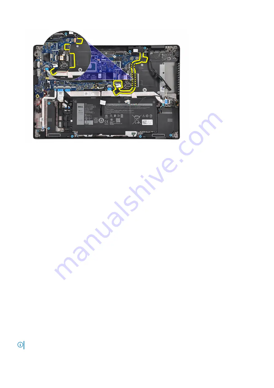
3. Adhere the tape to secure the tweeter-speaker cable to the top side of the bottom chassis.
4. Adhere the system-board rubber sticker to the tweeter-speaker cable.
5. Adhere the mylar tape to secure the tweeter-speaker cable to the keyboard bracket.
6. Adhere the tape to secure the tweeter-speaker cable to the audio daughter-board flexible flat cable and I/O daughter-board.
7. Connect the touch-screen cable (for computers shipped with a touch screen), display cable, IR-camera cable (for computers
shipped with an IR camera), and sensor daughter-board cable (for computers shipped with a sensor board) to the system
board.
8. Place the display-cable bracket on the system board.
9. Align the screw holes on the display-cable bracket with the screw holes on the system board.
10. Replace the two screws (M2x2) to secure the display-cable bracket to the system board.
11. Route the WLAN-antenna cables through the routing guides and connect them to the respective connectors on the system
board.
12. Align and place the WLAN bracket into its slot on the system board.
13. Replace the screw (M2x2) to secure the WLAN bracket to the system board.
Next steps
1. Install the
.
2. Install the
.
After working inside your computer
.
Smart card reader
Removing the smart card reader
Prerequisites
Before working inside your computer
.
2. Remove the
.
3. Remove the
or the
, whichever applicable.
About this task
NOTE:
This procedure applies only to computers shipped with a smart card reader installed.
58
Removing and installing components
Summary of Contents for P110F
Page 18: ...18 Removing and installing components ...
Page 36: ...36 Removing and installing components ...
Page 46: ...46 Removing and installing components ...
Page 61: ...Removing and installing components 61 ...
Page 70: ...70 Removing and installing components ...


