16.
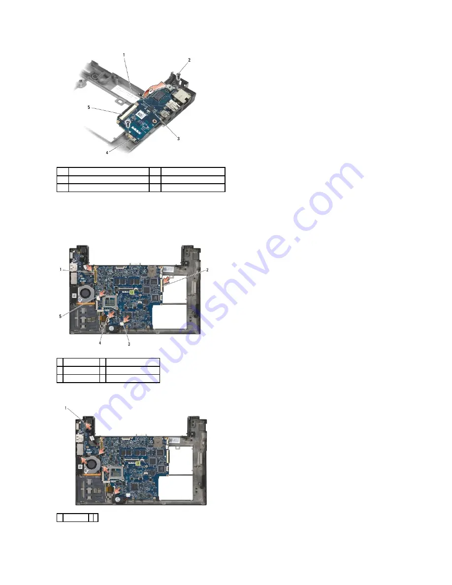
Disconnect the right I/O board cable from the system board by gently pulling on the connector release.
17.
Disconnect the smart card reader cable from the system board by gently lifting up on the release latch.
18.
Disconnect the fan and speaker cables from the system board.
19.
Remove the five M2 x 3-mm screws securing the system board assembly to the base assembly.
1
base assembly
2
screws (2)
3
right I/O board
4
guide pins (2)
5
connector release
1 DC power cable 2 right I/O board cable
3 speaker cable
4 smart card reader cable
5 fan cable
1 screws (5)
Summary of Contents for Latitude E4200
Page 68: ...Back to Contents Page ...


