Identifier
GUID-CC648B28-FBF9-4A6F-BB11-4C6C2FA3D08A
Status
Released
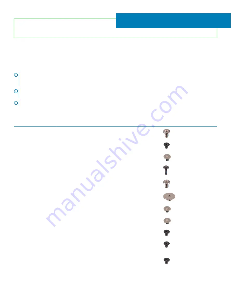
Screw list
NOTE:
When removing screws from a component, it is recommended to note the screw type, the quantity of screws, and then
place them in a screw storage box. This is to ensure that the correct number of screws and correct screw type is restored when
the component is replaced.
NOTE:
Some computers have magnetic surfaces. Ensure that the screws are not left attached to such surface when replacing a
component.
NOTE:
Screw color may vary with the configuration ordered.
Table 1. Screw list
Component
Secured to
Screw type
Quantity
Screw image
Base cover
Palm-rest and keyboard
assembly
M2.5x4
6
Battery
System board
M2x3
4
Display panel
Display back-cover and
antenna assembly
M2x2.5
4
Fan
System board
M2x5
2
Hinges
Palm-rest and keyboard
assembly
M2.5x4
4
Hinge brackets
Display back-cover and
antenna assembly
M2.5x2.5
6
Hinge brackets
Display back-cover and
antenna assembly
M2x2
2
I/O board
Palm-rest and keyboard
assembly
M2x2
2
Power-button
Palm-rest and keyboard
assembly
M2x3
2
Power button with
fingerprint reader
(optional)
Palm-rest and keyboard
assembly
M2x3
2
Solid-state drive
System board
M2x3
1
5
Screw list
15
Summary of Contents for Inspiron 3480
Page 8: ...Flea power release 138 8 Contents ...
Page 21: ...Replacing the base cover 21 ...
Page 23: ...Removing the battery 23 ...
Page 31: ...Removing the wireless card 31 ...
Page 35: ...Removing the coin cell battery 35 ...
Page 39: ...Removing the fan 39 ...
Page 43: ...Removing the heat sink 43 ...
Page 52: ...52 Removing the hard drive ...
Page 57: ...Removing the touchpad 57 ...
Page 61: ...Removing the speakers 61 ...
Page 65: ...Removing the I O board 65 ...
Page 69: ...5 Lift the palm rest and keyboard assembly at an angle Removing the display assembly 69 ...
Page 72: ...72 Removing the display assembly ...
Page 76: ...76 Removing the power button board ...
Page 81: ...Removing the system board 81 ...
Page 87: ...Removing the power button with fingerprint reader 87 ...
Page 91: ...Removing the power adapter port 91 ...
Page 95: ...Removing the palm rest and keyboard assembly 95 ...
Page 100: ...100 Removing the display bezel ...
Page 104: ...104 Removing the camera ...
Page 113: ...Removing the display hinges 113 ...
Page 117: ...Removing the display cable 117 ...
Page 121: ...Removing the display back cover and antenna assembly 121 ...


