


2 - 50
Chapter 2 Operation of Diag.
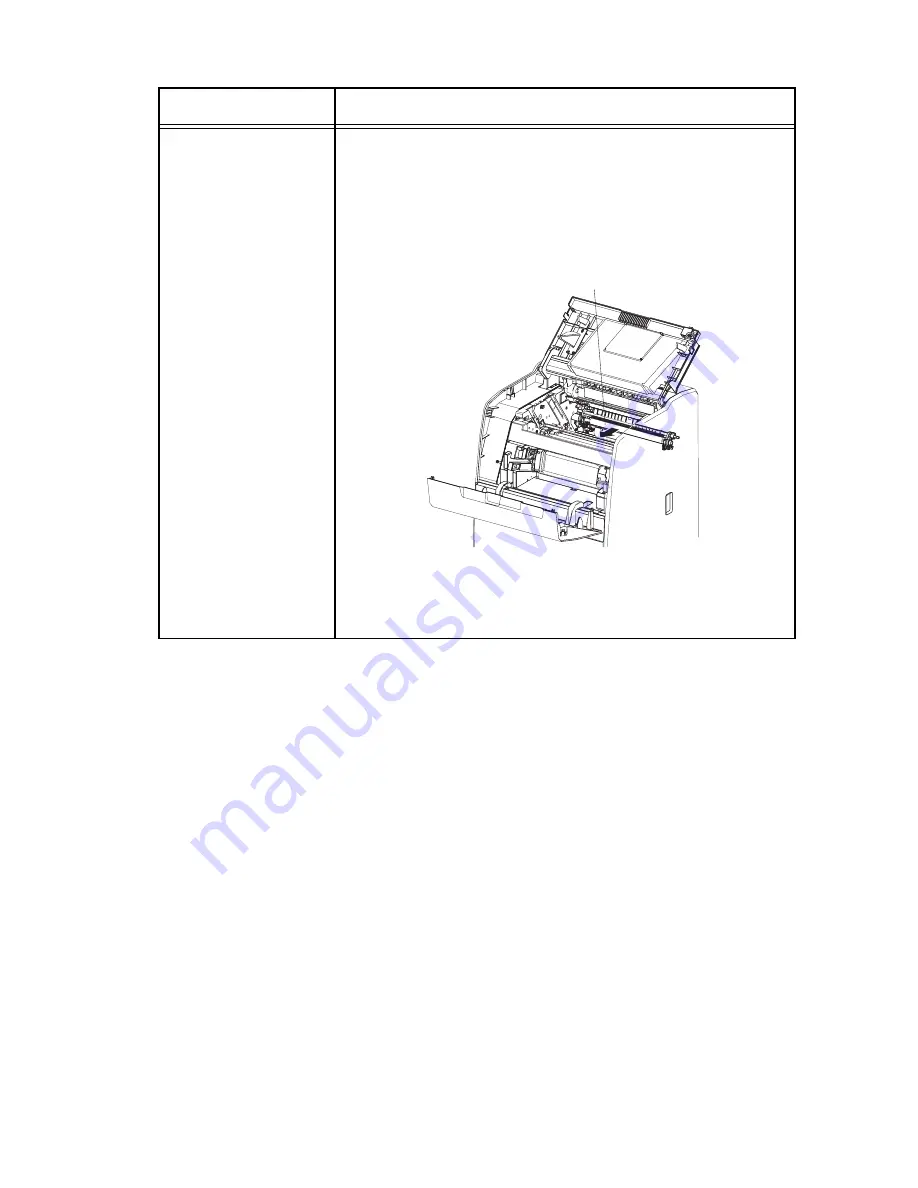
2nd BTR Retract Motor
(DO-14)
NOTE: This procedure is for the technical staff. The
customer’s procedure is the 1, 5 and 6.
1) Turn on the power and enter the Diagnostic Mode.
2) Open the Front door and the Top Cover and then remove the IBT.
3) Cheat the safety Interlock System.
4) Execute the DO-12 and confirm the moving of 2nd BTR. (The
customer can confirm the motor noise only.)
5) Press the “Cancel” key to stop test.
6) Remove the cheater and reseat the IBT.
7) Close the Top Cover and the Front Door.
Clutch and Solenoid name
(Diag. Code)
Confirmation procedure
Leg_Sec02_053FA
2nd BTR
Summary of Contents for 3010cn - Color Laser Printer
Page 1: ...Dell 3010cn Service Manual 14 Jan 2010 ...
Page 10: ...Intro 8 4 5 4 Caution label for ROS Leg_Sec001_010LA ...
Page 21: ...Intro 19 5 Reattach the control board cover to the printer ...
Page 27: ...Chapter 2 Operation of Diag Chapter 2 Operation of Diag CONTENTS ...
Page 113: ...3 15 Chapter 3 Removal and Replacement Procedures RRPs Blank Page ...
Page 155: ...3 57 Chapter 3 Removal and Replacement Procedures RRPs Blank Page ...
Page 191: ...3 93 Chapter 3 Removal and Replacement Procedures RRPs Blank Page ...
Page 201: ...3 103 Chapter 3 Removal and Replacement Procedures RRPs Blank Page ...
Page 215: ...3 117 Chapter 3 Removal and Replacement Procedures RRPs Blank Page ...
Page 229: ...3 131 Chapter 3 Removal and Replacement Procedures RRPs Blank Page ...
Page 235: ...3 137 Chapter 3 Removal and Replacement Procedures RRPs Blank Page ...
Page 239: ...3 141 Chapter 3 Removal and Replacement Procedures RRPs Blank Page ...
Page 247: ...3 149 Chapter 3 Removal and Replacement Procedures RRPs Blank Page ...
Page 251: ...3 153 Chapter 3 Removal and Replacement Procedures RRPs Blank Page ...
Page 261: ...3 163 Chapter 3 Removal and Replacement Procedures RRPs Blank Page ...
Page 293: ...3 195 Chapter 3 Removal and Replacement Procedures RRPs Blank Page ...
Page 315: ...3 217 Chapter 3 Removal and Replacement Procedures RRPs Blank Page ...
Page 319: ...3 221 Chapter 3 Removal and Replacement Procedures RRPs Blank Page ...
Page 325: ...3 227 Chapter 3 Removal and Replacement Procedures RRPs Blank Page ...
Page 351: ...3 253 Chapter 3 Removal and Replacement Procedures RRPs Blank Page ...
Page 355: ...3 257 Chapter 3 Removal and Replacement Procedures RRPs Blank Page ...
Page 399: ...3 301 Chapter 3 Removal and Replacement Procedures RRPs Blank Page ...
Page 435: ...3 337 Chapter 3 Removal and Replacement Procedures RRPs Blank Page ...
Page 445: ...3 347 Chapter 3 Removal and Replacement Procedures RRPs Blank Page ...
Page 457: ...3 359 Chapter 3 Removal and Replacement Procedures RRPs Blank Page ...
Page 467: ...3 369 Chapter 3 Removal and Replacement Procedures RRPs Blank Page ...
Page 470: ...3 372 Chapter 3 Removal and Replacement Procedures RRPs Blank Page ...
Page 494: ...5 10 Chapter 5 Parts List PL 2 1 250 Paper Cassette Illustration ...
Page 496: ...5 12 Chapter 5 Parts List PL 3 1 250 Paper Feeder 1 3 Illustration ...
Page 498: ...5 14 Chapter 5 Parts List PL 3 2 250 Paper Feeder 2 3 Illustration ...
Page 502: ...5 18 Chapter 5 Parts List PL 4 1 MSI Illustration ...
Page 506: ...5 22 Chapter 5 Parts List PL 5 2 PH Assy 2 2 Illustration ...
Page 508: ...5 24 Chapter 5 Parts List PL 6 1 Transfer Illustration ...
Page 510: ...5 26 Chapter 5 Parts List PL 7 1 Xero Illustration ...
Page 512: ...5 28 Chapter 5 Parts List PL 8 1 ROS Illustration ...
Page 516: ...5 32 Chapter 5 Parts List PL 9 2 DEVE 2 2 Illustration ...
Page 524: ...5 40 Chapter 5 Parts List PL 12 2 ELEC 2 2 Illustration ...
Page 526: ...5 42 Chapter 5 Parts List PL 14 1 500 Paper Cassette Illustration ...
Page 528: ...5 44 Chapter 5 Parts List PL 14 2 500 Paper Feeder 1 3 Illustration ...
Page 530: ...5 46 Chapter 5 Parts List PL 14 3 500 Paper Feeder 2 3 Illustration ...
Page 534: ...5 50 Chapter 5 Parts List PL 15 1 Legal Paper Cassette Illustration ...
Page 583: ...6 46 Chapter 6 Principles of Operation ...
Page 592: ...7 7 Chapter 7 Wiring Diagrams and Signal Information Blank Page ...
Page 616: ...Chapter 8 Printer Specifications Chapter 8 Printer Specifications CONTENTS ...


