


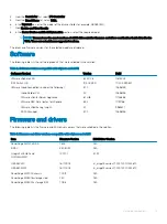


Validated components
Validated components refer to the hardware components, and the software and firmware versions that have been validated. The versions
that are listed in the following section are the recommended minimum for this release to match all of the deployment steps listed in this
guide.
Topics:
•
•
•
Using the VMware Compatibility Guide
•
•
Hardware components
The following hardware components were used in the validation of this solution.
NOTE:
Cloud Foundation automatically configures vSAN disk groups, which requires following a few rules for drive population:
•
Identical drive configurations in each target host
•
There must be one size for all cache drives, as well as one size for all capacity drives
•
The number of capacity drives in a host is cleanly divisible by the number of cache drives (that is, the result is a whole number)
Table 1. Hardware components
Manufacturer
Model
Description
Specifications
Dell EMC
PowerEdge MX7000
Chassis
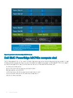
Dell EMC
PowerEdge MX740c
Compute sled
2x Xeon Gold processor, 256 GB
RAM, Cache drives
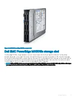
Dell EMC
PowerEdge MX5016s
Storage sled
12 Gbps SAS, Capacity drives
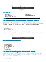
Dell EMC
PowerEdge MX5000s
SAS Fabric switch IOM
12 Gbps SAS
Dell EMC
Networking MX9116n
Network fabric switching engine IOM
Dell EMC
Networking MX7116n
Network fabric expander IOM
Dell EMC
Networking MX5108n
Network switch IOM
Dell EMC
HBA330 MX
Disk controller—internal drives
Dell EMC
HBA330 MMZ
Disk controller—PowerEdge
MX5016s drives
Dell EMC
BOSS MX
Boot/OS device
BOSS Card MX, 2x 256 GB M.2,
RAID-1 vDisk
Toshiba
PX05SMB
vSAN cache drive
800 GB, 12 Gbps SAS SSD, 2.5"
Samsung
PM1635a
vSAN capacity drive
1.6 TB, 12 Gbps SAS SSD, 2.5"
QLogic
QL41232HMKR
Network interface card
Slot Mezz 1A, 2 ports x 25 GbE
4
Validated components
11
Summary of Contents for PowerEdge MX7000
Page 1: ...Dell EMC VMware Cloud Foundation for PowerEdge MX7000 Deployment Guide ...
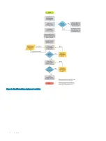
Page 8: ...Figure 1 Cloud Foundation deployment workflow 8 Overview ...
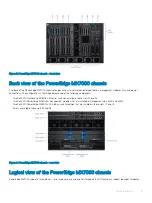
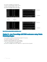
Page 27: ...Figure 19 Dual PowerEdge MX7000 enclosure configuration Physical layout 27 ...
Page 29: ...Figure 20 MX9002m Management module cabling Physical layout 29 ...
Page 30: ...Figure 21 Connectivity between FSE modules and FEM modules 30 Physical layout ...
Page 31: ...Figure 22 Uplinks to customer network environment Physical layout 31 ...
Page 42: ...Figure 25 MX9002m Management Module cabling 42 Networking requirements ...
Page 43: ...Figure 26 Connectivity between FSE modules and FEM modules Networking requirements 43 ...
Page 44: ...Figure 27 Uplinks to customer network environment 44 Networking requirements ...


