


4
From the
Search For
list, select
I/O Controller
.
5
From the
Brand Name
list, select
DELL
.
6
In the
Keyword
box, enter the model of the disk controller, for example, HBA330 MX.
7
Click
Update and View Results
.
8
In the
Server Device and Model Information
section, select the required model.
NOTE:
You must use the exact versions of vSAN disk controller firmware and driver combination that is listed in the
VCG. These are not minimum supported versions.
The driver and firmware versions for the selected model are displayed.
Software
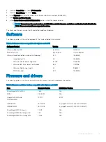
The following table lists the software products that were validated in the solution:
Table 2. Software versions compatible with vSphere and vSAN
Software Product
Version
Build
VMware vSphere ESXi
6.7 EP 06
11675023
IOM Switch OS
10.4.0E.R4S
10.4.0E.R4S.347
VMware Cloud Foundation (includes the following):
3.7.0
12696155
Cloud Builder VM
2.0
12696155
VMware vCenter Server Appliance
6.7 U1b
11726888
VMware NSX Data Center for vSphere
6.4.4
11197766
VMware vRealize Log Insight
4.7
9983377
SDDC Manager
3.7.0
12696155
Firmware and drivers
The following table lists the firmware and ESXi driver versions that were validated in the solution:
Table 3. Firmware and driver versions compatible with vSphere and vSAN
Item
Firmware Version
ESXi Driver Version
PowerEdge MX740c BIOS
1.6.13
N/A
iDRAC
3.30.30.30
N/A
QLogic 2x25 GbE and
QL41232HMKR
14.07.07
3.7.9.1
HBA 330 MX
16.17.00.03
lsi_msgpt3 version 17.00.01.00-1OEM.670
HBA 330 MMZ
16.17.00.03
lsi_msgpt3 version 17.00.01.00-1OEM.670
PowerEdge MX7000 chassis
1.00.10
N/A
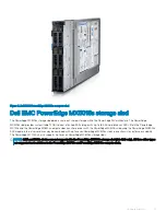
PowerEdge MX5016s storage sled
2.40
N/A
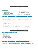
PowerEdge MX5000s storage IOM
1.0.9.6
N/A
Validated components
13
Summary of Contents for PowerEdge MX7000
Page 1: ...Dell EMC VMware Cloud Foundation for PowerEdge MX7000 Deployment Guide ...
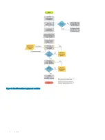
Page 8: ...Figure 1 Cloud Foundation deployment workflow 8 Overview ...
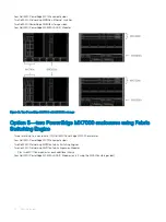
Page 27: ...Figure 19 Dual PowerEdge MX7000 enclosure configuration Physical layout 27 ...
Page 29: ...Figure 20 MX9002m Management module cabling Physical layout 29 ...
Page 30: ...Figure 21 Connectivity between FSE modules and FEM modules 30 Physical layout ...
Page 31: ...Figure 22 Uplinks to customer network environment Physical layout 31 ...
Page 42: ...Figure 25 MX9002m Management Module cabling 42 Networking requirements ...
Page 43: ...Figure 26 Connectivity between FSE modules and FEM modules Networking requirements 43 ...
Page 44: ...Figure 27 Uplinks to customer network environment 44 Networking requirements ...