

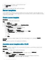


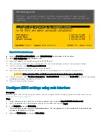


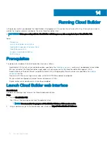


Figure 41. IPv4 configuration page
8
Enter the
IPv4 Address
,
Subnet Mask
, and the
Default Gateway
, and then press Enter to confirm.
9
Select
DNS Configuration
, and then press Enter.
10 Enter the IP addresses of the DNS servers and FQDN of the host.
11 Press Esc to return to the main menu, and then press Y to confirm the changes and restart the management network.
12 From the main menu, click
Test Management Network
.
The target IP addresses and DNS hostname are pre-populated.
13 Press Enter to perform the network test, and after the test is completed, press Enter to return to the main menu.
CAUTION:
If the network test fails, troubleshoot and resolve the issues before proceeding further.
14 From the main menu, select
Troubleshooting Options
>
Enable ESXi Shell
, and then select
Enable SSH
(required during validation
and deployment phases) to enable the ESXi shell.
15 Press Esc to return to the main menu.
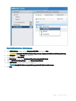
Configure ESXi settings using web interface
Prerequisite
Before configuring ESXi settings using web interface, you must configure the ESXi settings using DCUI. For more information, see
Configure ESXi settings—using DCUI
.
Steps
1
Using a web browser, go to the ESXi host-level management web interface at
https://<ESXi Host Address>/ui
.
2
Enter the credentials that were created during the ESXi installation, and then click
Log in
.
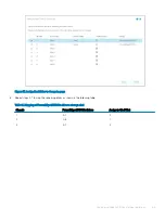
3
In the
Navigator
pane, click
Networking
.
The current port groups on the host are displayed by default. One is configured with VLAN information that is entered during
installation and the other is still at zero.
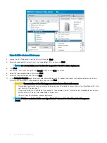
4
Right-click
VM Network
and then click
Edit settings
.
70
Deploy ESXi to cluster nodes
Summary of Contents for PowerEdge MX7000
Page 1: ...Dell EMC VMware Cloud Foundation for PowerEdge MX7000 Deployment Guide ...
Page 8: ...Figure 1 Cloud Foundation deployment workflow 8 Overview ...
Page 27: ...Figure 19 Dual PowerEdge MX7000 enclosure configuration Physical layout 27 ...
Page 29: ...Figure 20 MX9002m Management module cabling Physical layout 29 ...
Page 30: ...Figure 21 Connectivity between FSE modules and FEM modules 30 Physical layout ...
Page 31: ...Figure 22 Uplinks to customer network environment Physical layout 31 ...
Page 42: ...Figure 25 MX9002m Management Module cabling 42 Networking requirements ...
Page 43: ...Figure 26 Connectivity between FSE modules and FEM modules Networking requirements 43 ...
Page 44: ...Figure 27 Uplinks to customer network environment 44 Networking requirements ...


