


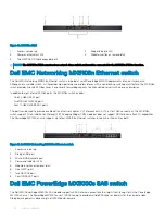


Figure 10. MX7116n FEM
1
Express service tag
2
Supported optic LED
3
Power and indicator LEDs
4
Module insertion or removal latch
5
Two QSFP28-DD fabric expander ports
NOTE:
The MX7116n FEM cannot act as a stand-alone switch and must be connected to the MX9116n FSE to function.
Dell EMC Networking MX5108n Ethernet switch
The Dell EMC Networking MX5108n Ethernet switch is targeted at small PowerEdge MX7000 deployments of one or two chassis.
Although not a scalable switch, it still provides high-performance and low latency with a non-blocking switching architecture. The MX5108n
switch provides line-rate 25 Gbps Layer 2 and Layer 3 forwarding capacity to all connected servers with no oversubscription.
In addition to eight internal 25 GbE ports, the MX5108n switch includes:
•
One 40 GbE QSFP+ port
•
Two 100 GbE QSFP28 ports
•
Four 10 GbE RJ45 BASE-T ports
The ports can be used to provide a combination of network uplinks, VLT interconnects (VLTi), or for FCoE connectivity. The MX5108n
switch supports FCoE Initialization Protocol (FIP) Snooping Bridge (FSB) mode but does not support NPG or direct attach FC capabilities.
The PowerEdge MX7000 chassis supports up to four MX5106n Ethernet switches in Fabric A or Fabric B, or both.
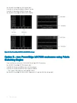
Figure 11. Dell EMC Networking MX5108n Ethernet switch
1
Express service tag
2
Storage USB port
3
Micro-B USB console port
4
Power and indicator LEDs
5
Module insertion or removal latch
6
One QSFP+ port
7
Two QSFP28 ports
8
Four 10GBASE-T ports
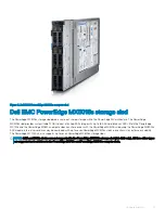
Dell EMC PowerEdge MX5000s SAS switch
The Dell EMC PowerEdge MX5000s SAS module supports x4 SAS internal connections to all eight front-facing slots in the PowerEdge
MX7000 chassis. The PowerEdge MX5000s uses T10 SAS zoning to provide multiple SAS zones or domains for the compute sleds.
Storage management is done using the OME-Modular console.
20
Hardware overview
Summary of Contents for PowerEdge MX7000
Page 1: ...Dell EMC VMware Cloud Foundation for PowerEdge MX7000 Deployment Guide ...
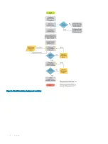
Page 8: ...Figure 1 Cloud Foundation deployment workflow 8 Overview ...
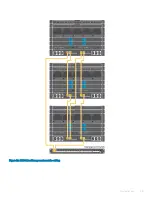
Page 27: ...Figure 19 Dual PowerEdge MX7000 enclosure configuration Physical layout 27 ...
Page 29: ...Figure 20 MX9002m Management module cabling Physical layout 29 ...
Page 30: ...Figure 21 Connectivity between FSE modules and FEM modules 30 Physical layout ...
Page 31: ...Figure 22 Uplinks to customer network environment Physical layout 31 ...
Page 42: ...Figure 25 MX9002m Management Module cabling 42 Networking requirements ...
Page 43: ...Figure 26 Connectivity between FSE modules and FEM modules Networking requirements 43 ...
Page 44: ...Figure 27 Uplinks to customer network environment 44 Networking requirements ...


