C1000 Series Service & Maintenance Manual
Service and Repair
SECTION IV
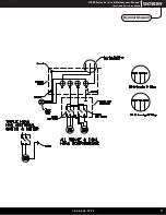
Fig. L
Fig. M
Fig.K
After removing the wiring from the compressor motor, the motor may be removed by unscrewing the air discharge hose on the front left
cylinder, and removing the four ½” nuts securing the head to the vibration isolation mounts.
2. Power Switches: The toggle switches located on the front center of the
compressor control the individual compressor motors. If the pressure
switch is operating correctly, remove the motor terminal cover on the back
of the desired compressor motor. With the power switch in the on “up”
position, check for voltage to the compressor motor as shown in Fig. K. If
the proper voltage is present, the power switch is good. If no voltage is
present at the motor, replace the corresponding power switch.
3. Compressor Motor (head): The compressor motor turns the compressor crankshaft to generate air
fl
ow to the system. If the correct
voltage is present on the L1 and L2 terminals as described in the testing procedure listed above, but the compressor hums and does not
start, the start capacitor is defective. If the correct voltage is present but nothing happens, the head is defective.
To replace the motor, it is not required to cut the spade terminals from the wiring (see Figures L and M) for proper disassembly without
cutting factory wiring.
1.800.624.2793
13
Unpacking
Electrical


