background image

C1000 Series Service & Maintenance Manual

Service and Repair

SECTION IV

PNEUMATIC

WARNING

: HIGH SYSTEM PRESSURES MAY CAUSE SERIOUS INJURY.

ALWAYS DEPRESSURIZE THE ENTIRE SYSTEM BEFORE ATTEMPTING TO SERVICE PNEUMATIC COMPONENTS.

1.  

Replacing the check valves.

 If a check valve failure occurs, the symptom will be air escaping through one of the compressor 

heads with the compressor NOT running. To replace a defective check valve, unscrew “counterclockwise” the air discharge hose 

fi

 tting 

from the appropriate compressor head. Once the air discharge hose is disconnected from the compressor head, the check valve, 
along with the discharge hose, may be removed from the discharge manifold by unscrewing the check valve ”counterclockwise”, and 
replaced with a new check valve. Reverse this process to reassemble the check valve / discharge hose assembly.

2.  

Replacing the Differential Filter Indicator.

 If the differential indicator becomes stuck in either the red OR green 

indicating position, the indicator needs replacement. Replace the differential 

fi

 lter indicator by unscrewing the entire assembly 

“counterclockwise” with a 15/16” - 6 point / box end wrench. Install the new indicator in the reverse order.

3. 

 Automatic Filter Float Drain.

 Unscrew the coalescing 

fi

 lter bowl from the 

fi

 lter head. Using a 9/16 wrench, unscrew the 

retaining nut on the bottom of the 

fi

 lter bowl. With the retaining nut removed, the automatic 

fl

 oat drain will be removed from the 

fi

 lter bowl. Replace in the reverse order. 

4.  

Replacing Desiccant Chamber.

 To replace the desiccant chamber, remove the rigid stainless steel tubing from the dryer 

bypass valve at the compression 

fi

 tting, located at the dryer bypass valve. Remove the top plumbing manifold assembly from the top 

of the desiccant chamber, by turning counterclockwise. Remove the electrical cord from the dryer purge valve by removing the Philips 
head retaining screw, and pulling the cable away from the valve timer block. Next, remove the 

fl

 exible discharge hose from the 

discharge side of the coalescing 

fi

 lter, and then unscrew the bottom manifold assembly from the bottom of the desiccant chamber.

Replace the desiccant chamber and reassemble in the reverse order.

1.800.624.2793

15

Unpacking

Electrical

Summary of Contents for C1103

Page 1: ...D C1203 D C2106 D C2206 D C3210 C Series COMPRESSOR Copyright 2006 DCI All Rights Reserved D C1103 D C1203 D C2106 D C2206 D C3210 C Series COMPRESSOR Compressor Service Maintenance Manual 92311 Rev...

Page 2: ...1 www dcionline com www dcionline com...

Page 3: ...SERVICE REPAIR INSTRUCTIONS A Troubleshooting Chart B Electrical 1 Replacing Pressure Switch 2 Replacing Power Switch 3 Replacing Compressor Head 4 Replacing Time Operated Purge Valve C Pneumatic 1 Re...

Page 4: ...service procedures before attempting to service this machine Our unique dryer purge system operates much differently than conventional air compressors Understanding the proper operation and design wil...

Page 5: ...ons 1 Single 1 horsepower compressor head on 20 gal Horizontal tank See Fig A 2 Dual 1 horsepower compressor heads on 20 gal Horizontal tank See Fig B 3 Dual 1 horsepower heads on 30 gal horizontal ta...

Page 6: ...5 C1203 3 95 1 20 34 24 29 5 230 6 7 10 C2106 7 95 2 20 34 24 29 5 115 26 8 30 C2206 7 95 2 20 34 24 29 5 230 13 4 15 C3210 11 85 3 30 46 26 36 230 21 1 30 NOTE ALL VOLTAGES ARE 5 MODEL NUMBER MAXIMUM...

Page 7: ...ttom of the filter bowl The compressed air also travels through the coalescing filter element which removes 99 998 of all particles down to 0 01 microns A filter change indicator located on the top of...

Page 8: ...e compressor cycles off C The Left timer knob on the purge valve controls the duration of the purge cycles This timer is factory preset and should not be adjusted The factory setting is at the maximum...

Page 9: ...C1000 Series Service Maintenance Manual Theory of Oporation Theory of Operation THEORY OF OPERATION While Not Running Electrical Schematic SECTION II 1 800 624 2793 7...

Page 10: ...e element first turn off the compressor motor switches Then turn off the Dryer bypass valve as shown in Fig E With dryer bypass valve in OFF position press the TEST button on the time operated purge v...

Page 11: ...floor Check the filter screen inside the filter strainer valve as shown in Fig G If the strainer shutoff valve is on and the screen is not clogged replace the Time Operated Purge Valve with DCI part N...

Page 12: ...breaker Ensure that supply voltage matches equipment ratings Check for loose wiring Check contact points and adjust or replace Bleed pressure from system to ensure proper starting Ensure supply volta...

Page 13: ...or replace intake filter element Clean Replace valve plate Air leaks compressor too small to meet demand Add ventilation and or cooling to equipment room Clean or replace solenoid valve assembly Left...

Page 14: ...oltage indicated should agree with the machine data plate either 115 or 230 volt AC If no voltage is present check the circuit breaker Fig I Fig J ELECTRICAL If the proper voltage is present on the ou...

Page 15: ...on up position check for voltage to the compressor motor as shown in Fig K If the proper voltage is present the power switch is good If no voltage is present at the motor replace the corresponding po...

Page 16: ...embly 2 Turn OFF the strainer shutoff valve in Fig N 3 Remove the valve and replace with DCI Part Number 2011 for 230 volt machines OR DCI Part Number 2848 for 115 volt models 4 Return the strainer sh...

Page 17: ...Replace the differential filter indicator by unscrewing the entire assembly counterclockwise with a 15 16 6 point box end wrench Install the new indicator in the reverse order 3 Automatic Filter Float...

Page 18: ...er 2006 Coalescing Element 2135 Check Valve 2135 Check Valve 2014 Drying Chamber Assembly Pressure Gauge 2011 Automatic Purge Valve 230 Volt OR 2848 Automatic Puge Valve 115 Volt 2009 Strainer Shut Of...

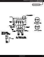
Page 19: ...C1000 Series Service Maintenance Manual Illustrated Parts Breakdown SECTION V Unpacking Electrical Schematic 1 800 624 2793 17...
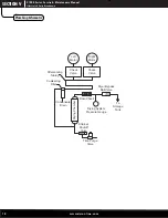
Page 20: ...ION V Unpacking Plumbing Schematic Left Motor Right Motor Check Valve Check Valve Aftercooling Tubing Coalescing Filter Condensate Drain Drying Chamber Flow Check Drying System Pressure Gauge Dryer By...

Page 21: ...1 800 624 2793 19...

Page 22: ...305 N Springbrook Road Newberg Oregon 97132 USA 503 538 8343 800 624 2793 www dcionline com...

Reviews: