32
Switching between different embedded audio sources
Example 2:
We have two mono mics each connected to a different HD camera. The embedded audio is then output from each
camera, HD-SDI, to the SE-2800 switcher. If we want to hear the audio from each camera as the video channels
are switched,
audio follows video
, then we would set up in the following way.
Press the
ENTER
key
in the
MENU
area of the SE-2800 keyboard to display the on screen menu on the HDMI 1
output.
Change the
Audio Association
settings in the menu system to show a value of 1 for each video input channel that
is associated with audio input 1. Then change to a value of 2 each video input channel that is associated with audio
input 2. Press the
ENTER
key to store the audio values chosen for each video input.
Change the
SDI Embedded Audio
setting
in the switcher’s menu system to show a value of Group 1 and Pair 1.
Press the
ENTER
key to store the audio values chosen for each video input.
Now exit the menu by pressing any wipe key and look at the
FIX / A+V button
in the wipes area
of the keyboard.
Select the
AUDIO-F-VIDEO
status with this button when looking at the status area of the HDMI
multi-view. The button will be off. The status area is located just below or near the Preview image
on the HDMI multi-view monitor.
When switching between the video sources the audio sources will also change. We can choose how the audio will
change sources, whether it be a clean cut (immediate switch) or some sort of transitioned change (cross fade or
fade out & in). To do this we would need to set up with the following menu options.
Auto Audio Mixing Type
User choice of
X type
or
V type
Tick selection
X type = A/B cross fade
V type = Fade out A then fade in B
T-Bar Audio Mixing Type
Tick selection of
Follow auto audio mixing type
(use above option)
By the end
(clean cut or immediate audio switch)
GPI / GPO Connections
The SE-2800 can be controlled externally via a simple contact closure GPI (General Purpose Interface) switch.
This could be a push button, foot switch or any relay or any circuit that is able to provide a simple contact closure.
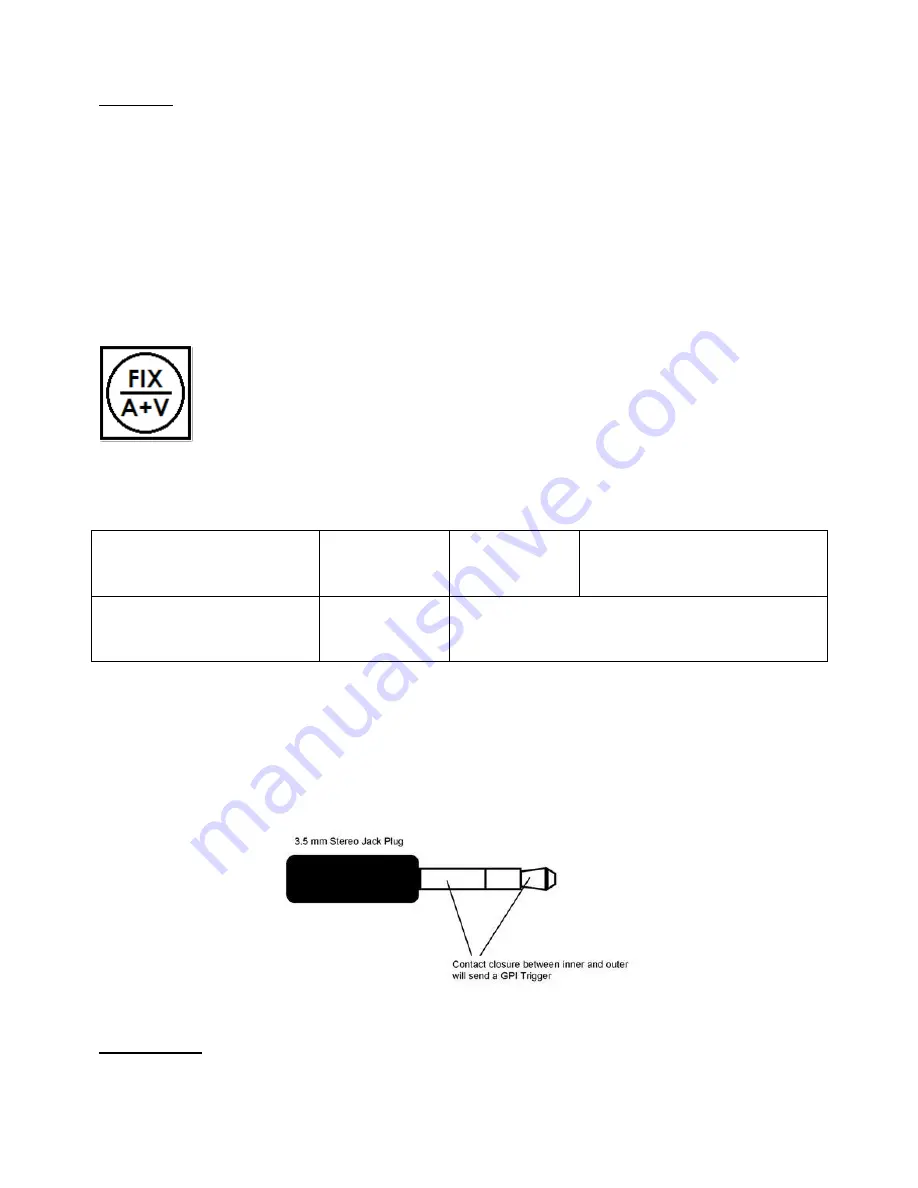
The GPI interface is a 3.5mm Jack Socket which is situated on the rear panel of the SE-2800. Contact closure
between the Outer and Inner contacts on the jack plug will trigger a user selected event. Power is supplied by the
SE-2800 and is less than 5V DC.
This GPI socket can also be used as a GPO socket to trigger record or playback events with other equipment such
as the Datavideo HDR-70 recorder.
SAFETY FIRST
The cabling required needs to be designed specifically to connect the SE-2800 to the chosen
record or playback device as they are not all the same. The cabling required can be made by yourself or a
competent technician. Please speak with your Dealer or local Datavideo office to get further help and advice.


