USE AND OPERATION
53
4
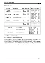
RESUME TABLE
STATUS
STATUS LED
INPUT STATUS
(*)
OUTPUT STATUS
(*)
SYSTEM
BOOTING UP
BLINKING GREEN (1Hz)
KEY
LOW
ENABLE
LOW
SYSTEM_ALARM
ON
POWER_ON
OFF
ENABLE_OUT
OFF
WAIT FOR START
STEADY GREEN
KEY
LOW
ENABLE
LOW
SYSTEM_ALARM OFF
POWER_ON
OFF
ENABLE_OUT
OFF
WARMING UP
BLINKING ORANGE (1Hz)
KEY
HIGH
ENABLE
LOW
SYSTEM_ALARM OFF
POWER_ON
OFF
ENABLE_OUT
OFF
STANDBY
SHUTTER CLOSED
STEADY ORANGE
KEY
HIGH
ENABLE
LOW
SYSTEM_ALARM OFF
POWER_ON
ON
ENABLE_OUT
OFF
READY
STEADY RED
KEY
HIGH
ENABLE
HIGH
SYSTEM_ALARM OFF
POWER_ON
ON
ENABLE_OUT
ON
STATUS
STATUS LED
OUTPUT STATUS
(*)
WARNING
INVALID START SEQUENCE
BLINKING ORANGE (2Hz)
SYSTEM_ALARM
OFF
POWER_ON
OFF
ENABLE_OUT
OFF
SYSTEM ERROR
BLINKING RED (2Hz)
SYSTEM_ALARM
ON
POWER_ON
OFF
ENABLE_OUT
OFF
(*) See paragraph 2.42.4.3 for more information.
4.1.1 ADVICE ON USING THE SYSTEM
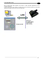
If the marking system is used in manual mode you need to connect Command Box connector as described
before. In this way you are able to control the marking system directly from the rack front panel.
If the marking system is used in automatic mode it is recommended to permanently enable Key and Enable
commands positioned on the rack front panel and to use remote signals (
EXT_KEY
and
EXT_ENABLE
)
available on the Command Box connector. This part is supplied with the product and you can wire external
controls to the connector contacts following the pin descriptions in paragraph 2.6.
Summary of Contents for VLASE IR 1PWX-TLS2
Page 1: ...USER S MANUAL VLASETM IR ...
Page 34: ...VLASETM IR 34 2 2 6 CONNECTION EXAMPLES Figure 27 Connection examples ...
Page 85: ...85 EXTERNAL LABEL PLACING Figure 67 Positioning of external labels rack ...
Page 86: ...86 Figure 68 Positioning of external labels resonator ...
Page 90: ...90 BLOCK DIAGRAM VLASETM SAFETY LOGIC DETAILS FOR AUTOMATIC PRODUCTION LINE ...
Page 108: ...108 APPENDIX G MECHANICAL DRAWINGS ...
Page 109: ...109 NOTE Please refer to Datalogic website for detailed drawings ...
Page 112: ......

