INSTALLATION AND SET UP
35
3
3 INSTALLATION AND SET UP
3.1 CONNECTIONS
This section of the manual describes the marking system wiring. Carry out the connecting operations as
described below.
WARNING!
Connect the components of the marking system together
WITHOUT
voltage in order to avoid risks to
the operator and to the marking system.
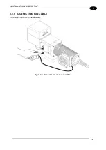
3.1.1 CONNECTING COMMAND BOX CABLE
Figure 28: Connecting Command Box cable.
NOTE:
The Command Box cable must always be inserted in order to use Enable and Key on the front panel
of the rack.
Summary of Contents for VLASE IR 1PWX-TLS2
Page 1: ...USER S MANUAL VLASETM IR ...
Page 34: ...VLASETM IR 34 2 2 6 CONNECTION EXAMPLES Figure 27 Connection examples ...
Page 85: ...85 EXTERNAL LABEL PLACING Figure 67 Positioning of external labels rack ...
Page 86: ...86 Figure 68 Positioning of external labels resonator ...
Page 90: ...90 BLOCK DIAGRAM VLASETM SAFETY LOGIC DETAILS FOR AUTOMATIC PRODUCTION LINE ...
Page 108: ...108 APPENDIX G MECHANICAL DRAWINGS ...
Page 109: ...109 NOTE Please refer to Datalogic website for detailed drawings ...
Page 112: ......


