VLASE
TM
IR
38
3
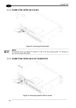
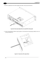
3) insert the optical fiber into the PG cable gland mounted on the rear panel of the rack.
Figure 33: Passing the optical fiber through the PG cable gland.
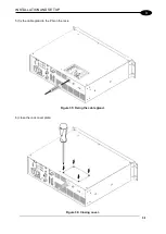
4) remove the optical fiber protection cap and tighten it to the fiber diode module paying attention not to soil
or scratch the fiber end.
Figure 34: Connection of the optical fiber.
Summary of Contents for VLASE IR 1PWX-TLS2
Page 1: ...USER S MANUAL VLASETM IR ...
Page 34: ...VLASETM IR 34 2 2 6 CONNECTION EXAMPLES Figure 27 Connection examples ...
Page 85: ...85 EXTERNAL LABEL PLACING Figure 67 Positioning of external labels rack ...
Page 86: ...86 Figure 68 Positioning of external labels resonator ...
Page 90: ...90 BLOCK DIAGRAM VLASETM SAFETY LOGIC DETAILS FOR AUTOMATIC PRODUCTION LINE ...
Page 108: ...108 APPENDIX G MECHANICAL DRAWINGS ...
Page 109: ...109 NOTE Please refer to Datalogic website for detailed drawings ...
Page 112: ......

