background image

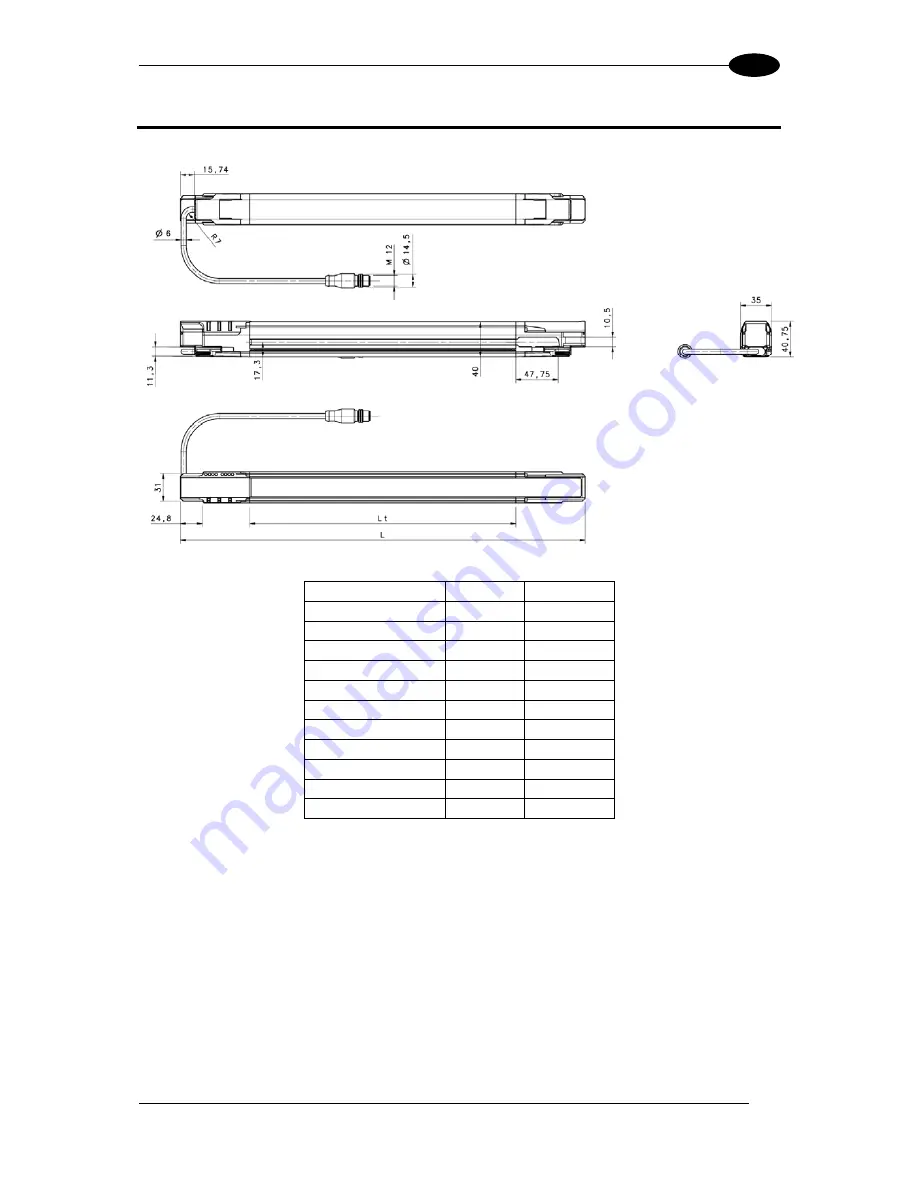
OVERALL DIMENSIONS 


77


13

13 OVERALL DIMENSIONS  


MODEL L

t

 (mm) 

L (mm) 

SG4-xx-030-OO-P 

150 

306,3 

SG4-xx-045-OO-P 

300 456,3 

SG4-xx-060-OO-P 

450 606,3 

SG4-xx-075-OO-P 

600 756,3 

SG4-xx-090-OO-P 

750 906,3 

SG4-xx-105-OO-P 

900 1056,3 

SG4-xx-120-OO-P 

1050 1206,3 

SG4-xx-135-OO-P 

1200 1356,3 

SG4-xx-150-OO-P 

1350 1506,3 

SG4-xx-165-OO-P 

1500 1656,3 

SG4-xx-180-OO-P 

1650 1806,3 

    xx = Resolution (14mm - 30mm) 
 

Summary of Contents for SG4-14-030-OO-P

Page 1: ...SG4 EXTENDED Instruction Manual ...

Page 2: ...d without express written consent from Datalogic Automation S r l Datalogic and the Datalogic logo are registered trademarks of Datalogic S p A in many countries including the U S A and the E U All brand and product names mentioned herein are for identification purposes only and may be trademarks or registered trademarks of their respective owners Datalogic shall not be liable for technical or edi...

Page 3: ......

Page 4: ...ce from reflecting surfaces 12 2 2 2 Distance between homologous devices 13 2 2 3 Emitter and Receiver Orientation 16 2 2 4 Use of deviating mirrors 16 2 2 5 Checks after first installation 17 3 MECHANICAL MOUNTING 19 4 ELECTRICAL CONNECTIONS 21 4 1 Notes on connections 24 5 ALIGNMENT PROCEDURE 26 6 FUNCTION SETTING 28 6 1 Reset to Factory configuration 30 6 2 Function List 31 7 FUNCTIONS 33 7 1 R...

Page 5: ...ing 65 8 DIAGNOSTIC 67 8 1 User interface 67 9 PERIODICAL CHECKS 71 9 1 GENERAL INFORMATION AND USEFUL DATA 71 9 2 WARRANTY 72 10 DEVICE MAINTENANCE 73 10 1 Product disposal 73 11 TECHNICAL DATA 74 12 LIST OF AVAILABLE MODELS 75 13 OVERALL DIMENSIONS 77 14 OUTFIT 78 15 ACCESSORIES 80 15 1 Brackets fixing 80 15 2 Muting lamp 83 15 3 Deviating mirrors 84 15 4 Columns and floor stands 86 15 5 Lens sh...

Page 6: ...the load 25 Fig 22 Incorrect connection of the load I 25 Fig 23 Incorrect connection of the load II 25 Fig 24 Incorrect connection of the load III 25 Fig 25 Behaviour of OSSDs 25 Fig 26 Description of the beams 26 Fig 27 Alignment timings 26 Fig 28 ACM configuration cycle 29 Fig 29 Safety report 30 Fig 30 Restart timings auto 33 Fig 31 Restart connection auto 33 Fig 32 Restart timings manual 34 Fi...

Page 7: ...timings 50 Fig 52 Override restart connection 51 Fig 53 Override restart timings auto 52 Fig 54 Override restart timings normal 53 FIG 55 PNP CONNECTION 63 Fig 56 PNP timings 63 FIG 57 NPN CONNECTION 64 Fig 58 NPN timings 64 Fig 59 No code 65 Fig 60 Code 1 and code 2 65 ...

Page 8: ...uarantees the check and the management of the beams that are sent and received through the units the microprocessor through some LEDs informs the operator about the general conditions of the safety light curtain both for settings and for diagnostics see chapter 6 and 8 ...

Page 9: ... SIL 3 Functional safety of electrical electronic programmable electronic safety related systems Part 2 Requirements for electrical electronic programmable electronic safety related systems EN 61508 3 1998 SIL 3 Functional safety of electrical electronic programmable electronic safety related systems Part 3 Software requirements EN 61508 4 1998 SIL 3 Functional safety of electrical electronic prog...

Page 10: ...the user or installing operator are preceded by a note The information provided in the paragraphs following this symbol is very important for safety and may prevent accidents Always read this information accurately and carefully follow the advice to the letter GUI The paragraphs containing descriptions reported on the GUI too are written with this character This manual contains all the information...

Page 11: ...ave some new important features Higher operating distance New profile compatible with SE accessories Advanced alignment function for receiver and transmitter units Muting function Partial muting Selectable muting timeout Override Override status Blanking function fixed and floating Teach in Tolerance Reduction Range Null dead zone the controlled height of the light curtain is equivalent to the lig...

Page 12: ...at constitute the sensitive area The resolution strictly depends on the part of the body to be protected R 14mm finger protection Type 4 R 30 mm hand protection Type 4 As shown in Fig 1 the resolution only depends on the geometrical characteristics of the lenses diameter and distance between centres and is independent of any environmental and operating conditions of the safety light curtain Operat...

Page 13: ...whole height of the light curtain Referring to the figure above the protected height is reported in the table here below Model Protected height mm SG4 xx 030 OO P 300 SG4 xx 045 OO P 450 SG4 xx 060 OO P 600 SG4 xx 075 OO P 750 SG4 xx 090 OO P 900 SG4 xx 105 OO P 1050 SG4 xx 120 OO P 1200 SG4 xx 135 OO P 1350 SG4 xx 150 OO P 1500 SG4 xx 165 OO P 1650 SG4 xx 180 OO P 1800 xx Resolution 14mm 30mm ...

Page 14: ...istance S K t1 t2 C where S Minimum safety distance in mm K Speed of the object limb or body approaching the dangerous area in mm sec t1 Response time of the ESPE in seconds see chapter 11 t2 Machine stopping time in seconds d Resolution of the system C Additional distance based on the possibility to insert the body or one of body parts inside the dangerous area before the protective device trips ...

Page 15: ...on the following formula is used S K T C where T t1 t2 t1 ESPE response time SE SR2 relay release time max 80 ms t2 Machine total stopping time C 8 d 14 for devices with resolution 40 mm D resolution In all cases if K 2000mm sec then S 500 mm Distance will have then to be recalculated using K 1600 mm sec WARNING the reference standard is EN ISO 13855 replaces EN 999 Safety of machinery Positioning...

Page 16: ...f only one beam of the SG4 EXTENDED safety light curtain is darkened while the press is moving down the mobile tool bar will stop Benefits The safety light curtain can be used in most bending operations thanks to its easy installation and compact dimensions As well as offering excellent reliability SG4 EXTENDED ensures increased plant productivity as it reduces the dead times necessary for machine...

Page 17: ...trol system must be able to stop the dangerous movement of the machine within the total machine stopping time T as reported in par 1 3 3 and during all working cycle phases Mounting and connection of the safety light curtain must be carried out by qualified personnel only according to the indications included in the special sections see chapters 2 3 4 5 and in the applicable standards The safety l...

Page 18: ...ect to be detected must be larger than the resolution level of the device The ESPE must be installed in a room complying with the technical characteristics indicated in chapter 11 Do not install anything close to strong and or flashing light sources or close to similar devices The presence of intense electromagnetic disturbances could affect device s correct operation This condition shall be caref...

Page 19: ...tain at a sufficient height in order to completely cover the access to the dangerous area Fig 6 becomes necessary Fig 5 Incorrect device positioning Fig 6 Correct device positioning Under standard operating conditions machine starting must not be possible while operators are inside the dangerous area When the installation of the safety light curtain very near to the dangerous area is not possible ...

Page 20: ...t the recognition of an object inside the controlled area Moreover if the RX receiver detects a secondary beam reflected by the side reflecting surface the object might not be detected even if the object interrupts the main beam DANGEROUS AREA Reflecting surface Reflecting surface Fig 9 Minimum distance from reflecting surfaces It is important to position the safety light curtain according to the ...

Page 21: ... operating distance m x tg 2 for operative distances 3 m 2 2 2 Distance between homologous devices If different safety devices have to be installed in adjacent areas the emitter of one device must not interfere dangerously with the receiver of the other device The TXB interfering device must be positioned outside a minimum Ddo distance from the TXA RXA emitter receiver couple axis Fig 11 Distance ...

Page 22: ...um installation distances relative to some operating distances Operating distance m Minimum installation distance m 3 0 3 6 0 4 10 0 5 19 0 6 WARNING the interfering device TXB must be positioned at the same Ddo distance calculated as shown above even if closer to TXA respect to RXA When several safety devices have to be installed in adjacent areas the interference between the emitter of one devic...

Page 23: ...d two possible solutions TX RX TX RX RX TX TX RX TX RX TX RX opaque surface Fig 13 Interference between adjacent light curtains If two light curtains have to be mounted near each other as reported in the first example of Fig 13 coding function can resolve this situation refer to par 7 12 NO YES YES ...

Page 24: ...ree different access sides using two mirrors placed at 45 with respect to the beams Fig 15 Use of deviating mirrors The operator must respect the following precautions when using the deviating mirrors The alignment of the emitter and the receiver can be a very critical operation when deviating mirrors are used Even very small displacements of the mirror is enough to lose alignment The use of Datal...

Page 25: ... after the first installation and before machine start up are listed hereinafter The controls must be carried out by qualified personnel either directly or under the strict supervision of the person in charge of machinery Safety Check that ESPE remains in SAFE state intercepting the beams along the protected area using the specific test piece TP 14 or TP 30 following the Fig 16 scheme Fig 16 Path ...

Page 26: ...e refer to chapter 2 The safety distance between the dangerous parts and ESPE must comply with the requirements indicated in chapter 2 A person must not access or remain between ESPE and the dangerous parts of the machine Access to the dangerous areas of the machine must not be possible from any unprotected area ESPE must not be disturbed by external light sources ensuring that it remains in NORMA...

Page 27: ...e on request see chapter 15 To mount the angled fixing brackets kit place the threaded pins metallic insert into the dedicated side seat of the terminator cap side light curtain closing cap slide the insert towards the metallic drawn profile groove Fix the bracket against the profile by tightening the M5 hexagonal nuts It s possible to slide the bracket group along their dedicated rail and fix it ...

Page 28: ...456 3 236 3 110 SG4 xx 060 OO P 606 2 306 2 150 SG4 xx 075 OO P 756 2 406 2 175 SG4 xx 090 OO P 906 1 506 1 200 SG4 xx 105 OO P 1056 1 606 1 225 SG4 xx 120 OO P 1206 966 150 453 SG4 xx 135 OO P 1356 1066 175 503 SG4 xx 150 OO P 1505 9 1166 200 553 SG4 xx 165 OO P 1655 9 1266 225 603 SG4 xx 180 OO P 1805 8 1366 250 652 9 xx Resolution 14mm 30mm ...

Page 29: ...hite cap that is present Take care that the terminator cap CVL 5196 see chapter 14 is connected on the top side of the light curtains If this connection misses Master and Slave units go in critical Communication failure N B since the RX connections are different for M12 12 poles of muting cable and M12 12 poles of blanking cable it s important to use the correct cable for each configuration connec...

Page 30: ...G1 50 B 002 M12 5 pin 1 24V brown 2 TEST white 3 0V blue 4 EARTH black 5 NOT USED grey M12 Connectors pinout 12 pin 5 pin MUTING CONFIGURATION LINE LAYOUT CONNECTION BEHAVIOUR RESET active on high level in failure lockout RESTART active on high level at runtime ALIGNMENT active on high level at startup OVERRIDE 1 active on high level at runtime OVERRIDE 2 active on low level at runtime EDM SEE PAR...

Page 31: ...RTH connect directly to earth BLANKING CONFIGURATION RECEIVER LINE LAYOUT CONNECTION BEHAVIOUR RESET active on high level in failure lockout RESTART active on high level at runtime ALIGNMENT active on high level at startup TEACH IN active on high level at runtime TOLERANCE active on high level at startup EDM SEE PAR 7 4 FOR CONNECTIONS must be ossds antivalent at runtime with edm enabled OSSD1 OSS...

Page 32: ...on must be located in such a way that the operator can check the protected area during any reset operation The device is already equipped with internal overvoltage and overcurrent suppression devices The use of other external components is not recommended Example connection to the safety relay Fig 20 Connection to safety relay The figures show the connection between the safety light curtains and t...

Page 33: ...m safety degree that the light curtain has to control Fig 21 Correct connection of the load Fig 22 Incorrect connection of the load I Fig 23 Incorrect connection of the load II Fig 24 Incorrect connection of the load III 115 usec 500 msec 1000 msec OSSD during safe behaviour OSSD2 OSSD1 24Vdc GND 24Vdc GND Fig 25 Behaviour of OSSDs NO NO YES NO ...

Page 34: ... figure shows that the first beam is located at the bottom edge of the light curtain near to led display The last beam is at the opposite near the terminator cap These two beams are the synchronization beams too 1st beam last beam Nth beam Fig 26 Description of the beams The Alignment function can be activated by simply keeping pressed the external normally open push button linked to RESET RESTART...

Page 35: ...he LEVEL on the RX unit is as high as possible and beams are not interrupted then verify that all LEVEL Led turn OFF if even one single beam is interrupted This verification shall be made with the special cylindrical Test Piece having a size suitable to the resolution of the device used see par 2 2 5 E Switch off and on the device in standard operating mode The alignment level is monitored also du...

Page 36: ...composed by 3 push buttons is present the purpose of the interface is to let the user set light curtain locally and without use of PC graphic user interface Setting interface is composed by a CONFIRM push button used to enter in BCM and to confirm the selected configuration a SELECT push button used to roll by different functions and an ENABLE push button to activate deactivate the current functio...

Page 37: ...ator there are different passwords that protect some functions of the GUI Operator Password System Integrator SystemIntegrator Maintainer Maintainer Machine Operator no password requested DEVICE SELECTION PARAMETERS SELECTION REPORT CHECK ESPE CHECK connection configure accept OPERATIONS NO ONE ACCESSING DANGEROUS MACHINE OPERATIONS NORMAL OPERATION SAFE NORMAL OPERATION PLANT STATUS ESPE STATUS F...

Page 38: ... Serial Number Configuration ID checksum of configuration parameters Fig 29 Safety report 6 1 RESET TO FACTORY CONFIGURATION User can also reset ESPE at factory configuration settings with the following push button action 1 press and keep pressed CONFIRM button for at least 9 sec but less than 30 sec otherwise the light curtin goes in lockout failure 2 the leds blink for a while then the light cur...

Page 39: ...to a blanking configuration and viceversa and since these 3 leds have 3 different meanings depending on the configuration the user has to pay attention to the configuration setting when decides to change configuration RX Function list in Muting operation Mode Led 3 ON Yellow Function Led Setting Led Status Coding 2 Code 1 Code 2 No Code Muting Blanking Selection 3 Muting Blanking EDM 4 Enabled Dis...

Page 40: ...3 Muting Blanking EDM 4 Enabled Disabled Restart mode 5 Auto Manual Floating Blanking Selection 6 7 Floating Blanking Disabled Floating Blanking 1 beam Floating Blanking 2 beams Reduced Res 4 beams Fixed blanking selection 8 1 Fixed Blanking Zone 2 Fixed Blanking Zones Tx Function list Function Led Setting Led Status Coding 2 Code 1 Code 2 No Code Range Selection 3 Long Short ...

Page 41: ...l Restart Automatic Restart when an opaque object is detected the ESPE enters in the SAFE condition Then after the object has been removed from the controlled area the ESPE begins its normal functioning again The response time is the time between the object introduction in the protected area and the OSSDs achieving the OFF state SAFE the recovery time is the time within OSSDs go in the ON state SA...

Page 42: ...TART brings the ESPE in failure lockout Fig 32 Restart timings manual In Manual Restart the RESET RESTART ALIGN input pin 3 of M12 12 poles RX side has to be connected to a 24VDC normally open contact Fig 33 Restart connection manual WARNING Carefully assess risk conditions and reset modes In applications protecting access to dangerous areas the automatic reset mode is potentially unsafe if it all...

Page 43: ...in 2 of M12 5 poles for at least 0 5 seconds The TEST disables the emission stage so the RX side sees interrupted all beams and the OSSD goes low within response time As shown in the timing diagram below the OSSDs go OFF BREAK status after 500msec plus a cycle time and after the response time of the light curtain OFF ON OFF ON TEST SAFE NORMAL OPERATION OSSDs status EMISSION status 500ms RESPONSE ...

Page 44: ...the case of failure on microprocessor for which a power cycle is necessary 5 sec normal failure 0Vdc 24Vdc Safety light curtain STATUS RESET Fig 35 Reset timings If the error is not removed the light curtain goes in lockout failure again 7 4 EDM The External Device Monitoring EDM function controls external devices by verifying the OSSDs status EDM enabled When EDM is enabled in PNP configuration i...

Page 45: ...lains the relationship between the cause OSSDs and the effect EDM with the maximum permissible delay Tc 350 msec time between OSSD OFF ON transition and EDM test To 100 msec time between OSSD ON OFF transition and EDM test two different times for the mechanical contact driven by a spring EDM disabled When EDM is disabled it s necessary to leave the EDM input floating PNP CONFIGURATION NPN CONFIGUR...

Page 46: ...e mounted When Long Range is selected on RX if TX is configured as Long Range the maximum operating distance is 20m 30mm resolution and 7m 14mm resolution if TX is configured as Short Range the maximum operating distance is 12m 30mm resolution and 4m 14mm resolution When Short Range is selected on RX if TX is configured as Long Range the maximum operating distance is 6m 30mm resolution and 2m 14mm...

Page 47: ...operating distance short range is indicated in those cases in which multiple couples of light curtains have to be mounted near and no code can be used Next tables resume for both resolution the different operating distances when the reduction range is changed Resolution 30mm RX Long Range RX Short range Long Range TX 20 6 Short range TX 12 4 Resolution 14mm RX Long Range RX Short range Long Range ...

Page 48: ...s If MUTING1 and MUTING2 inputs are activated by two Muting sensors or actuators these should be correctly connected and positioned in order to avoid undesired Muting or potentially dangerous conditions for the operator MUTING1 and MUTING2 can t be activated simultaneously State of Muting is signalled by an external Muting Lamp that can be connected to the light curtains with the pin 10 of the M12...

Page 49: ...detected ESPE goes in Lamp Failure Lock Out state and shows the related message on the display refer to chapter 11 for informations about the lamp 7 7 3 Typical muting application and safety light curtain connection Fig 40 Typical Muting Application The figure above shows a typical muting application a protection installed on a conveyor should allow the pack passing by but not the worker The ESPE ...

Page 50: ...t and start the sequence from the beginning Fig 41 T muting timings The sensors named A1 A2 are connected to the same muting input MUTING1 and the sensors named B1 B2 are connected to MUTING2 The sensors that end with 1 are on the same side of the light curtain and are on the opposite side of the sensors that end with 2 D is the distance at which the sensors A1 A2 or B1 B2 have to be mounted it de...

Page 51: ... of ACM The muting function ends after a time that is a multiple of the activation delay between the two sensors this time is m T12 The value of m T12 multiplier can be chosen by the user In BCM this value is 2 by default The maximum activation delay between MUTING1 and MUTING2 can be set by the user from a minimum of 1 sec to a maximum of 16 sec After this time if the user wants to enter in mutin...

Page 52: ...rom right to left only B sensor can t be intercepted first if this happens the device doesn t enter muting function V indicates a constant speed As a consequence d1 is fixed according to the following formula d1 cm V m s T12 s 100 Fig 44 L muting connection BCM Configuration Muting Direction T bidirectional Led 6 ON Green L monodirectional Led 6 OFF ACM Configuration Muting Direction ...

Page 53: ...ing function still continues to exist This is not compliant with the 61496 1 rule and the user is warned about it Fig 45 Muting timeout The user can personalize the timeout from 10 minutes to 1080 minutes that correspond to 18 hours with steps of 1 minute the user can even set infinite timeout In this case there s a warning that alerts the user that this timeout is not IEC 61496 1 compliant BCM Co...

Page 54: ... filter on muting inputs low high or high low transitions of MUTING signals are considered valid only if maintained for a time Tf greater than 100ms If this function is disabled the logical level of the muting sensors corresponds to the wire level ACM Configuration Muting Filter Fig 46 Muting filter disabled Fig 47 Muting filter enabled ...

Page 55: ...elect a maximum of 5 muting zones each defined with the following parameters Position first beam of muting zone starting from user display cap Dimension number of beams of muting zone ACM Configuration Partial Muting Selection Check Partial Muting to enable function Click button to add a new muting zone X to remove a selected one Choose correct parameters for selected zone Both Dimension and Posit...

Page 56: ... 12 poles connector RX Fig 48 Override connection Necessary condition for override request to be accepted is ESPE in SAFE state and at least one muting sensor intercepted When such condition is verified user interface visualizes override attention status with both red OSSD led and alignment leds blinking OVERRIDE ATTENTION STATUS Then an override request is accepted only if signals at OVERRIDE X i...

Page 57: ...rride conditions present Fig 49 Override timings level trigger Edge Trigger override engaged on contacts closing until at least one muting sensor is intercepted In this case the override state rests even if the override contacts are released The device exits the override state when one of the following events happens the muting sensors are deactivated T muting or the muting sensor are deactivated ...

Page 58: ...Trigger Mode more than 120s the Override goes low in any case after a maximum of 120s ACM mode Override timeout is the maximum duration of override This time can be chosen by the user from a minimum of 1 minute to a maximum of 256 minutes After timeout the override ends even if the conditions for its activation are still existing and the override inputs are active OVERRIDE STATUS is an output sign...

Page 59: ...selection can be achieved only if the light curtain is in Manual Restart the user can select the type of Override Restart Normal or Auto The user has to connect the RESET RESTART ALIGN input pin 3 of M12 12 poles RX side to a 24VDC normally open contact Fig 52 Override restart connection ...

Page 60: ...e recovery time and the time of restart high greater or equal to 500msec so this time can be any value between 500ms and 5s When override ends if the beams are free the OSSDs go to normal operation state OVERRIDE STATUS is an output signal that informs the user if the override inputs are active with override conditions present Fig 53 Override restart timings auto ACM Configuration Auto Override Re...

Page 61: ...he recovery time and the time of restart high greater or equal to 500msec so this time can be any value between 500ms and 5s When override ends if the beams are free the ESPE goes to interlock state and a restart is required to achieve normal operation state OVERRIDE STATUS is an output signal that informs the user if the override inputs are active with override conditions present Fig 54 Override ...

Page 62: ...umber of beams within the controlled area is being intercepted The user can even connect a lamp whose characteristics are reported in chapter 11 to indicate that a blanking function is active The use of the lamp is not mandatory for a light curtain in blanking mode The lamp begins to blink in the following cases the light curtain is in any fixed blanking mode and the object is removed from the bla...

Page 63: ...lerance function can be activated by keeping pressed at startup the 24VDC normally open contact on Tolerance signal pin 9 of M12 12 poles RX With Tolerance active the object can move 1 beam above or below the blanking zone If object moves more than 1 beam out of the blanking zone ESPE locks out in Blanking Tolerance Fault Tolerance function is useful if there is the possibility that the object can...

Page 64: ... Blanking with total surveillance Floating Blanking with total surveillance allows the object to move freely inside the light curtain s controlled area The blanked beams must be occupied and therefore the object has to be inside the controlled area of the light curtain to remain in normal operation state This function can be set only by means of ACM 7 9 4 Floating Blanking with partial surveillanc...

Page 65: ...g blanking configuration zones haven t a fixed position it is valid only in fixed blanking This function can be set only by means of ACM 7 9 8 Tolerance There are 2 types of tolerance position and dimension Position Tolerance It indicates the number of beams in blanking zone that can be intercepted above and below the blanking zone without making the OSSDs switch off In presence of wide vibrations...

Page 66: ...ith the blinking of some leds in the user interface as shown below Tolerance indication Tolerance active Led 3 blinking YELLOW Tolerance affects the ESPE resolution Take care to the new resolution in order to calculate a new mechanical mounting POSITION TOLERANCE DIMENSION TOLERANCE ...

Page 67: ...Floating Blanking Floating Blanking Disabled Led 6 ON Green Led 7 ON Green Floating Blanking 1 beam with partial surveillance Led 6 ON Green Led 7 OFF Floating Blanking 2 beams with partial surveillance Led 6 OFF Led 7 ON Green Reduced Resolution 4 Led 6 OFF Led 7 OFF Floating blanking disabled no Floating Blanking allowed Floating Blanking 1 beam ESPE stays in NORMAL OPERATION if 1 or 0 beams are...

Page 68: ... be chosen by the user REDUCED RESOLUTION ACM Configuration GUI calculates the maximum object size in mm that can intercept ESPE without causing SAFE STATE Effective ESPE resolution changes depending on the different value assigned to parameter N Safety distance should be calculated according to effective resolution N value 14mm ESPE effective resolution 30mm ESPE effective resolution 1 23mm 49mm ...

Page 69: ...ith increased tolerance top over this zone fixed blanking zones only are allowed under this zone fixed and total surveillance blanking zones are allowed FLOATING BLANKING WITH TOTAL SURVEILLANCE Floating objects can move up or down intercepting different beams while moving the objects can t overlap nor change relative positions Object must be always present in the protected area and intercept the ...

Page 70: ... different beams while moving they can even get out of the protected area or intercept a number of beams minor than the configured one Adjacent to this zone fixed blanking only can be configured with such fixed blanking zones floating objects can overlap and even change relative positions without causing the switching of the OSSDs ...

Page 71: ...0mm and the maximum length of each slave is 1200mm For the correct connection of the units in a cascade configuration the right cables have to be used CVL 5193 CVL 5194 CVL 5195 on chapter 15 A safe auto recognition procedure at startup is implemented it automatically detects cascade topology and correctly address units In order to allow auto recognition it s mandatory to connect the termination c...

Page 72: ...ION IN THIS CONFIGURATION THE LOAD IS CONNECTED BETWEEN 24VDC AND OSSD OUTPUT IN NORMAL OPERATION OSSDS OUTPUT VOLTAGE IS 0V WHEN AN OPAQUE OBJECT INTERCEPTS THE BEAMS THE STATUS OF OSSDS CHANGES FROM LOW TO HIGH FIG 57 NPN CONNECTION Fig 58 NPN timings ...

Page 73: ...void possible interferences that can lead to a dangerous situation If the user has to install the light curtains nearer than the minimum allowed distance he should take care to install the TX of the first light curtain on the same side of the RX of the second Fig 59 No code Code 1 or Code 2 When the user has to install two light curtains at a distance that is lower than the minimum distance allowe...

Page 74: ... No Code Led 5 and 6 OFF Code 1 Led 5 ON Red Led 6 OFF Code 2 Led 5 OFF Led 6 ON Green Normal Operation TX side No Code Led 5 and 6 OFF Code 1 Led 5 ON Red Led 6 OFF Code 2 Led 5 OFF Led 6 ON Green The function can be set by BCM of both RX and TX devices The number of available codes is two BCM Configuration Coding Selection TX and RX No Code Led 2 OFF Code 1 Led 2 ON Red Code 2 Led 2 ON Green ACM...

Page 75: ...ION Off On Blink Indifferent SUGGESTED ACTION ALIGNMENT NOT ALIGNED 1ST SYNC ENGAGED LAST SYNC ENGAGED MININUM SIGNAL LEVEL MAXIMUM SIGNAL LEVEL NORMAL OPERATION MANUAL RESTART ONLY INTERLOCK FREE BEAMS user can restart device in normal operation activating RESTART line INTERLOCK INTERRUPTED BEAMS user must free protected area before activating RESTART line NORMAL OPERATION OSSD ON MAXIMUM ALIGNME...

Page 76: ...NCE ACTIVE check effective ESPE resolution and intentional activation of tolerance function NORMAL OPERATION MUTING ONLY MUTING ACTIVE if unexpected OSSD OFF with muting active check partial muting configuration OVERRIDE ACTIVE OSSD ON muting lamp flashing OVERRIDE ATTENTION STATUS trigger override button to force OSSDs ON OVERRIDE TIMINGS FAILURE check and repeat override activation sequence chec...

Page 77: ...N FAILURE Check cascade connection and correct mounting of terminator cap Activate RESET line BCM CONFIGURATION FAILURE Re operate Basic Configuration If error persists contact Datalogic Automation Technical Support ACM CONFIGURATION FAILURE Re operate Advanced Configuration If error persists contact Technical Support Make sure the most recent version of the GUI available on www datalogic com is i...

Page 78: ...ST if undesired Test check TEST line connection EMISSION FAILURE FAILURE ON MICROPROCESSOR Activate RESET line If error persists contact Datalogic Automation Technical Support FAILURE ON OPTICS Activate RESET line If error persists contact Datalogic Automation Technical Support BCM CONFIGURATION FAILURE Re operate Basic Configuration If error persists contact Datalogic Automation Technical Support...

Page 79: ...rson between ESPE and machine dangerous parts is not possible nor it is possible for him her to stay there Access to the dangerous area of the machine from any unprotected area is not possible The ESPE and the external electrical connections are not damaged The frequency of checks depends on the particular application and on the operating conditions of the safety light curtain 9 1 GENERAL INFORMAT...

Page 80: ...es adaptations not made by DATALOGIC AUTOMATION personnel tampering with the device etc accidents or crashes even due to transportation or by force majeure causes other causes not depending from DATALOGIC AUTOMATION If the device does not work send both units receiver and emitter to DATALOGIC AUTOMATION The Customer is responsible for all transport charges and damage risks or material loss during ...

Page 81: ...uch pressure on the surface in order to avoid making it opaque Please do not use on plastic surfaces or on light curtain painted surfaces alcohol or solvents wool or synthetic cloths paper or other abrasive materials 10 1 PRODUCT DISPOSAL Under current Italian and European laws DATALOGIC S p A is not obliged to take care of product disposal at the end of its life DATALOGIC S p A recommends to disp...

Page 82: ...rnal Lamp 20mA min 300 mA max Connections M12 12 poles M12 5 poles for receiver muting models M12 12 poles for receiver blanking models M12 5 poles for emitter for both models Cables length for power supply 50 m max OPTICAL DATA Emitting light λ Infrared LED 950 nm Resolution 14 30 mm Operating distance 0 2 20 m for 30 mm 0 2 7 m for 14 mm Ambient light rejection IEC 61496 2 MECHANICAL AND ENVIRON...

Page 83: ...4 SG4 14 180 OO P 1800 192 33 65 14 SG4 30 030 OO P 300 16 13 16 30 SG4 30 045 OO P 450 24 14 18 30 SG4 30 060 OO P 600 32 15 20 30 SG4 30 075 OO P 750 40 16 23 30 SG4 30 090 OO P 900 48 17 25 30 SG4 30 105 OO P 1050 56 18 27 30 SG4 30 120 OO P 1200 64 19 29 30 SG4 30 135 OO P 1350 72 19 32 30 SG4 30 150 OO P 1500 80 20 34 30 SG4 30 165 OO P 1650 88 21 36 30 SG4 30 180 OO P 1800 96 22 38 30 With t...

Page 84: ...O P 24 2 24 2 46 0 46 SG4 14 135 OO P 26 0 50 5 SG4 14 150 OO P 27 7 55 0 SG4 14 165 OO P 29 5 59 5 SG4 14 180 OO P 31 2 64 0 Master response time AIC OFF msec Tmaster Slave response time AIC OFF msec Tslave Master response time AIC ON msec Tmaster AIC Slave response time AIC ON msec Tslave AIC SG4 30 030 OO P 11 9 11 9 14 6 15 SG4 30 045 OO P 12 8 12 8 16 8 17 SG4 30 060 OO P 13 7 13 7 19 1 19 SG...

Page 85: ...4 xx 045 OO P 300 456 3 SG4 xx 060 OO P 450 606 3 SG4 xx 075 OO P 600 756 3 SG4 xx 090 OO P 750 906 3 SG4 xx 105 OO P 900 1056 3 SG4 xx 120 OO P 1050 1206 3 SG4 xx 135 OO P 1200 1356 3 SG4 xx 150 OO P 1350 1506 3 SG4 xx 165 OO P 1500 1656 3 SG4 xx 180 OO P 1650 1806 3 xx Resolution 14mm 30mm ...

Page 86: ...SG4 EXTENDED INSTRUCTION MANUAL 78 14 14OUTFIT Angled fixing bracket with threaded pins metallic insert ...

Page 87: ...OUTFIT 79 14 Terminator cap CVL 5196 Tool for BCM configuration The tool for BCM configuration when not used can be inserted in the profile groove by making it enter from the top of the light curtain ...

Page 88: ...gled fixing bracket Antivibration support Angled fixing bracket Orientable support Antivibration support MODEL DESCRIPTION CODE ST KSTD Fixing brackets 4 pcs kit 95ACC1670 ST K4OR Orientable supports 4 pcs kit 95ACC1680 ST K6OR Orientable supports 6 pcs kit 95ACC1690 ST K4AV Antivibration supports 4 pcs kit 95ACC1700 ST K6AV Antivibration supports 6 pcs kit 95ACC1710 ...

Page 89: ...xing bracket Orientable support 61 2 67 2 73 9 79 9 73 9 79 9 52 8 65 7 56 2 21 1 78 4 52 5 20 25 20 20 25 25 Fixing bracket Antivibration support 26 6 5 58 0 5 60 70 3 83 9 84 7 5 58 3 20 25 20 25 25 20 73 9 79 9 56 2 56 9 71 2 71 9 73 9 79 9 Fixing bracket Orientable support Antivibration support MODEL DESCRIPTION CODE ST KP4MP Fixing brackets 4 pcs kit 95ASE1100 ST KP6MP Fixing brackets 6 pcs k...

Page 90: ...SG4 EXTENDED INSTRUCTION MANUAL 82 15 Cascade bracket MODEL DESCRIPTION CODE ST KCASCADE SG EXTENDED Bracket 95ASE2110 ...

Page 91: ...Ø4 5 45 100 Ø5 110 Ø54 70 MODULO SU LMS 1A LMS 1 SUPPORTO SU LMS 1B LMS 1 MODEL DESCRIPTION CODE LMS Muting lamp 95ASE1830 LMS 1 Modular Muting lamp 95ACC1990 LMS 2 Muting lamp horizontal mounting 95ACC2000 LMS 3 Muting lamp vertical mounting 95ACC2010 SU LMS 1A Basic module for LMS 1 95ACC2020 SU LMS 1B Tower module for LMS 1 95ACC2030 ...

Page 92: ...L1 mm L2 mm L3 mm CODE SG DM 600 Deviating mirror version 600 mm 545 376 580 95ASE1680 SG DM 900 Deviating mirror version 900 mm 845 676 880 95ASE1690 SG DM 1200 Deviating mirror version 1200 mm 1145 976 1180 95ASE1700 SG DM 1650 Deviating mirror version 1650 mm 1595 1426 1630 95ASE1710 SG DM 1900 Deviating mirror version 1900 mm 1845 1676 1880 95ASE1720 ...

Page 93: ...ACCESSORIES 85 15 Fixing kit MODEL DESCRIPTION CODE ST DM Kit STAND ALONE 95ASE1940 ...

Page 94: ...0 Column and floor stand H 800 mm 800 30x30 95ACC1730 SE S 1000 Column and floor stand H 1000 mm 1000 30x30 95ACC1740 SE S 1200 Column and floor stand H 1200 mm 1200 30x30 95ACC1750 SE S 1500 Column and floor stand H 1500 mm 1500 45x45 95ACC1760 SE S 1800 Column and floor stand H 1800 mm 1800 45x45 95ACC1770 ...

Page 95: ...s 95ASE1520 SG LS 1350 Lens Shield H 1350mm 5pcs 95ASE1530 SG LS 1500 Lens Shield H 1500mm 5pcs 95ASE1540 SG LS 1650 Lens Shield H 1650mm 5pcs 95ASE1550 SG LS 1800 Lens Shield H 1800mm 5pcs 95ASE1560 SG LS 2 050 Lens Shield H 500mm 5pcs 95ASE1570 SG LS 3 080 Lens Shield H 800mm 5pcs 95ASE1580 SG LS 4 090 Lens Shield H 900mm 5pcs 95ASE1590 SG LS 4 120 Lens Shield H 1200mm 5pcs 95ASE1600 NOTE Each p...

Page 96: ...ective stand H 1000mm 1000 95ASE2250 SG PSB 1200 Protective stand H 1200mm 1200 95ASE2260 SG PSB 1650 Protective stand H 1650mm 1650 95ASE2270 SG PSB 1900 Protective stand H 1900mm 1900 95ASE2280 Fixing kit MODEL DESCRIPTION CODE ST PS4 SG SE Kit 4pcs for protect ive stands mounting 95ASE1750 ST PS6 SG SE Kit 6pcs for protect ive stands mounting 95ASE1760 ...

Page 97: ...15 15 7 PLATE FOR PROTECTIVE STANDS MODEL DESCRIPTION CODE SG P Plate kit for SG PSG 95ASE2290 15 8 TEST PIECE MODEL DESCRIPTION CODE TP 14 Test piece Ø 14mm L 300mm 95ACC1630 TP 30 Test piece Ø 30mm L 300mm 95ACC1650 ...

Page 98: ...SG4 EXTENDED INSTRUCTION MANUAL 90 15 15 9 SG4 DONGLE ETHERNET ADAPTOR MODEL DESCRIPTION CODE SG4 DONGLE ETHERNET ADAPTOR 95ASE2080 ...

Page 99: ... curtain and the type 4 safety relay of the SE SR2 series operating in the automatic Restart mode on the left and manual Restart mode with monitoring on the right MODEL DESCRIPTION CODE SE SR2 Type 4 safety relay 3 NQ 1 NC 95ACC6170 MODEL DESCRIPTION CODE CS ME 03VU24 Y14 EDM Relay Box 95ASE1270 ...

Page 100: ...al 50 m UL2464 95A252700 CS A1 10 U 03 12 pole M12 cable axial 3 m UL2464 95A252720 CS A1 10 U 05 12 pole M12 cable axial 5 m UL2464 95A252730 CS A1 10 U 10 12 pole M12 cable axial 10 m UL2464 95A252740 CS A1 10 U 15 12 pole M12 cable axial 15 m UL2464 95A252750 CS A1 10 U 25 12 pole M12 cable axial 25 m UL2464 95A252760 CS A1 10 U 50 12 pole M12 cable axial 50 m UL2464 95A252770 TX PIG TAIL CABLE...

Page 101: ...side and a M12 12 poles in the other RX MUTING PIG TAIL CABLE This is the Pig Tail cable that must be always used for RX UNIT SG4 EXTENDED when you configure it in MUTING MODE and DON T USE SG4 DONGLE It has a 18 poles socket in one side and a M12 5 poles plus M12 12 poles in the other MODEL DESCRIPTION CODE CS G1 70 B 002 SG EXTENDED BLANKING RX 0 2m 95A252830 CS R1 75 B 002 SG EXTENDED MUTING RX...

Page 102: ...N MANUAL 94 15 Cascade cables MODEL DESCRIPTION CODE CS F1 80 B 01 SG EXTENDED CASCADE 1m 95A252840 CS F1 80 B 005 SG EXTENDED CASCADE 0 5m 95A252850 MODEL DESCRIPTION CODE CS F1 80 B 0005 SG EXTENDED CASCADE 0 05m 95A252860 ...

Page 103: ...nfiguration The following figures show respectively the dimensions of single active arms of single passive arms and the corresponding fixing bracket stand alone MODEL DESCRIPTION CODE SG AS ARM SINGLE ACTIVE ARM WITH RRX SENSORS V2 95ASE1841 SG PR ARM SINGLE PASSIVE ARM WITH REFLECTORS V2 95ASE1851 SG CB C MUTING ARMS MOUNTING BRACKET KIT 95ASE1930 ...

Page 104: ...et mounted of single passive arms with fixing bracket mounted of double active arms with fixing bracket mounted of double passive arms with fixing bracket mounted ACTIVE PASSIVE ARMS L ACTIVE PASSIVE ARMS T MODEL DESCRIPTION CODE SG L ARMS ACTIVE PASSIVE ARMS L COUPLE V2 95ASE1861 SG T ARMS ACTIVE PASSIVE ARMS T COUPLE V2 95ASE1871 ...

Page 105: ...ACCESSORIES 97 15 SG4 EXTENDED BRACCI ATTIVO PASSIVO L SG4 EXTENDED BRACCI ATTIVO PASSIVO T ...

Page 106: ...e ESPE connected to machine control system When the sensor is enabled during standard operating conditions it switches to disabled status FINAL SWITCHING DEVICE FSD part of the control system involving machine safety conditions It breaks the circuit to the machine primary control element MPCE when the output signal switching device OSSD becomes inactive PROTECTIVE DEVICE device having the function...

Page 107: ...mitting unit installed in the opposite position generates an optical curtain i e the detecting area RISK probability of occurrence of an injury and severity of the injury itself CROSSING HAZARD situation under which an operator crossing the area controlled by the safety device and this latter stops and keeps the machine stopped until the hazard is eliminated and then enters the dangerous area Now ...

Page 108: ...www datalogic com ...

Reviews: