MATRIX 120™ REFERENCE MANUAL
62
5
5.3 FIELDBUS CONNECTION
CAUTION:
Matrix 120 readers do not have Auxiliary Serial interfaces.
Therefore neither data monitoring nor device configuration can be performed
through this interface.
Once the Matrix 120 device is configured in DL.CODE for HMS Fieldbus
communication the Main Serial channel is no longer available.
Therefore it is recommended to make these configurations when connected to
DL.CODE through either the Ethernet interface (using CAB-ETH-Mxx) or the
USB interface (using CAB-1021).
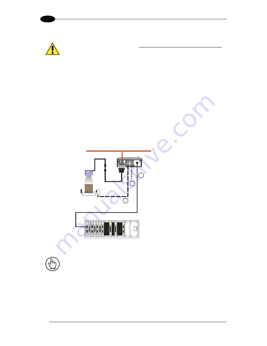
In this layout a single reader functions as a Slave node on a Fieldbus network. The data is
transmitted to the Host through an accessory Fieldbus interface board installed inside the
CBX500 connection box (i.e. BM300 Profibus or BM400 DeviceNet).
Other I/O devices connected to the CBX can be controlled from the Fieldbus Host through
the Matrix reader.
When One Shot or Phase Mode operating mode is used, the reader can be activated by an
External Trigger (photoelectric sensor) when the object enters its reading zone.
Figure 51
– Fieldbus Interface Point-to-Point Layout
NOTE:
Matrix 120 Ethernet models support EtherNet/IP, Modbus TCP and
PROFINET-IO Fieldbus interfaces without the use of external Fieldbus
modules. See the Ethernet Layouts.
CAB-1011
Matrix 120
1
2
3
Fieldbus Interface (Profibus, DevicNet, etc.)
Other I/O devices
External Trigger (for One Shot or Phase Mode)
Fieldbus Host
10-30 Vdc Power
CBX500 with
Host Interface Module (Fieldbus)


