Setup
14
Gryphon™ I GD44XX/GBT4400/GM440X
Insertion of the Scanner in its Cradle
To be sure that proper charging of battery is in progress, verify that the Red
LED of the cradle is steady on when the scanner is placed into its powered
cradle. The Green LED of the base indicates that the battery is fully charged.
If there are other conditions of cradle's LEDs, verify that the scanner is prop-
erly placed in the cradle.
Given the long battery life and the great ergonomics of the GBT/GM44 scan-
ner, it's not needed to place the scanner in the cradle after each barcode
reading transaction. Depending on the intensity of use, the scanner may
only need to be placed in its cradle at the end of the working shift.
Connecting the Base Station
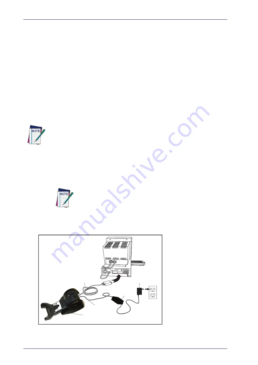
Figure 7 shows how to connect the Base Station to a terminal, PC or other
host device. Turn off the host before connection and consult the manual for
that equipment (if necessary) before proceeding. Connect the interface cable
before applying power to the Base Station.
The Gryphon GBT4400 can be set up to require a PIN code when connecting to the host. If you
are connecting to a system that uses a custom security PIN, follow the procedure in "Connect-
ing the Base when Security Pin is Enabled" on page
. For information on how to configure
this feature, see
Base Station Connection and Routing:
Fully insert the Power Cable and Interface
(I/F) Cable connectors into their respective ports in the underside of the Base
Station (see Figure 7). Then connect to an AC Adapter, and plug the AC
power cord into the (wall) outlet.
Gryphon Wireless can also be Powered by the Terminal. When powered by the
Terminal, the battery charger is automatically set as Slow charge.
For some specific interfaces or hosts or lengths of cable, the use of an exter-
nal power supply may be recommended for full recharging capability (see
on page 303 for more details).
Figure 7. Connecting the Base Station
Base
Station
I/F Cable
AC/DC
Adapter
DC Power
Cord
Wall plug
Connector
Summary of Contents for Gryphon I GM440 Series
Page 42: ...Setup 32 Gryphon I GD44XX GBT4400 GM440X...
Page 46: ...Enter Exit Programming Mode 36 Gryphon I GD44XX GBT4400 GM440X NOTES...
Page 60: ...Enter Exit Programming Mode 50 Gryphon I GD44XX GBT4400 GM440X NOTES...
Page 102: ...Enter Exit Programming Mode 92 Gryphon I GD44XX GBT4400 GM440X NOTES...
Page 248: ...238 Gryphon I GD44XX GBT4400 GM440X NOTES...
Page 308: ...References 298 Gryphon I GD44XX GBT4400 GM440X NOTES...
Page 338: ...Keypad 328 Gryphon I GD44XX GBT4400 GM440X A B C D E F...
Page 348: ...Scancode Tables 338 Gryphon I GD44XX GBT4400 GM440X NOTES...


