DataVS1
Series
Instruction
Manual
36
6.6.2.
Expert Protocol
Selection of the inspection number 15 (001111)
Protocol Description
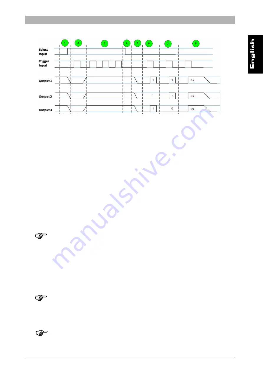
The Expert protocol for Inspection switching on sensor is based on an 8 phases handshake. According
to this protocol the sensor makes available an ACKNOWLEDGE message, representing a feedback on
the Inspection switching operation.
Five are the digital I/O PIN involved in the Expert protocol:
PIN 1: Select Input. It is used in the first 4 phases of the handshake, to alert the sensor
of an incoming Inspection switching request.
PIN 8: Trigger Input. It is used to communicate to the sensor the Slot number of the
Inspection to switch to and to retrieve Inspection switching ACKNOWLEDGE.
PIN 4: Output 1.
PIN 5: Output 2.
PIN 6: Output 3.
Following a description of each phase.
Phase 1: Select Input HIGH. ALL sensor outputs LOW.
Select Inputs signal (from PLC to sensor) switches from LOW (0V) to HIGH (24V), representing an
Inspection switching request. As a reaction the sensor sets all outputs to LOW.
Note
: in the worst case the time interval occurring between the instant when the Select Inputs
signal arrives to the sensor and the instant when the sensor set outputs to LOW can vary
depending on the current running Inspection. After receiving the Select Input signal the sensor
will finish the current Inspection cycle and then will rise down outputs.
Phase 2: Trigger Input HIGH. All sensor outputs HIGH.
The Trigger Input is set from PLC first time HIGH. The sensor sets all outputs to HIGH, entering the wait
for Inspection selection phase.
Phase 3: Inspection selection.
The sensor counts any incoming Trigger Input pulses as long as the Select Input is HIGH.
Note
: a timeout T1 will end phase 3 if Select Input signal doesn’t go LOW within 4 seconds. If
T1 occurs the Inspection selection will be ignored and the sensor will resume the previous
running Inspection.
Phase 4: Select Input LOW. Inspection selection verification.
The sensor performs an integrity verification on the number of received Trigger Input pulses.
Note
: this phase can take MIN_PULSE_DUR milliseconds at least.


