Data I/O
FLX500
Chptr 3
—28—
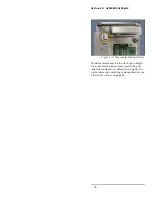
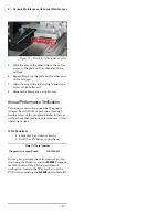
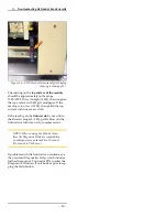
Figure 15—The bottom of a Programmer Module
allows access to the actuating screws when power to
the programmer is unavailable.
3.
Slide the Actuator Plate out from the pro-
grammer.
4.
Remove the Socket Adapter in the usual
way. For help removing the adapter, see the
on-screen Help.
Fiducial Scan Errors
If the
FLX500
fails to program after the PNP Head
scans the modules, there may be a problem with
the scanning.
NOTE: For accurate scanning, the fiducials
and sensors must be clean and the FLX cover
must be closed. For cleaning instructions,
see Cleaning the Fiducials and Sensors on
page 12.
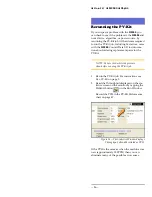
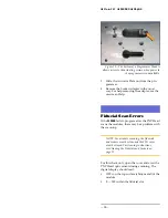
For this check only, open the cover and view the
PNP Head optic sensor during scanning. The
digital display should read:
•
1000+ on the top surface (shiny, metal) of the
module
•
0 — 500 within the fiducial slot
Summary of Contents for FLX500
Page 4: ... Data I O FLX500 ii ...
Page 12: ... Data I O FLX500 Chptr 1 8 blank page ...
Page 28: ... Data I O FLX500 Chptr 2 24 blank page ...
Page 40: ... Data I O FLX500 Chptr 4 36 blank page ...
Page 42: ... Data I O FLX500 Chptr 5 38 Daily Sign off Clean the sockets page 10 Date Initials Notes ...
Page 43: ...5 Sign off Charts Daily Sign off 39 Daily Sign off Date Initials Notes ...
Page 44: ... Data I O FLX500 Chptr 5 40 Daily Sign off Date Initials Notes ...
Page 45: ...5 Sign off Charts Daily Sign off 41 Daily Sign off Date Initials Notes ...
Page 46: ... Data I O FLX500 Chptr 5 42 Daily Sign off Date Initials Notes ...
Page 48: ... Data I O FLX500 Chptr 5 44 Weekly Sign off Date Initials Notes ...
Page 52: ... Data I O FLX500 Chptr 5 48 blank page ...
Page 57: ... FLX500 ...

