25
To extend the life of your
sharpener, its recommend a
routine maintenance program be
put in place. Every
120-machine hrs is suggested, or
more often if necessary.
WARNING
: Remove the plug before
carrying out any adjustment, servicing or
maintenance.
Vacuum system:
Optional but recommended
.
Using a dust extraction system can improve the
sharpening life of the machine. Unplug vacuum
from power source. Check filter or canister on a
regular basis.
Wheel cleaning:
These wheels are maintenance free from truing
and dressing but will need cleaning periodically.
After removing the wheel from the unit, saturate
the wheel with any type of oil-less solvent, such
as Automotive Brake Cleaner. It is helpful to use
a soft bristle brush and lightly brush the
saturated wheel, loosening the impacted
grinding particles. Re-saturate the wheel to flush
out any loosened debris.
Always clean a brand new wheel before
using.
If after cleaning wheel, the drills still
discolor or burn, the wheel life may be
exhausted and the wheel will need to be
replaced.
Recalibrating Material Removal
After a wheel change, verify and/or recalibrate
material removal.
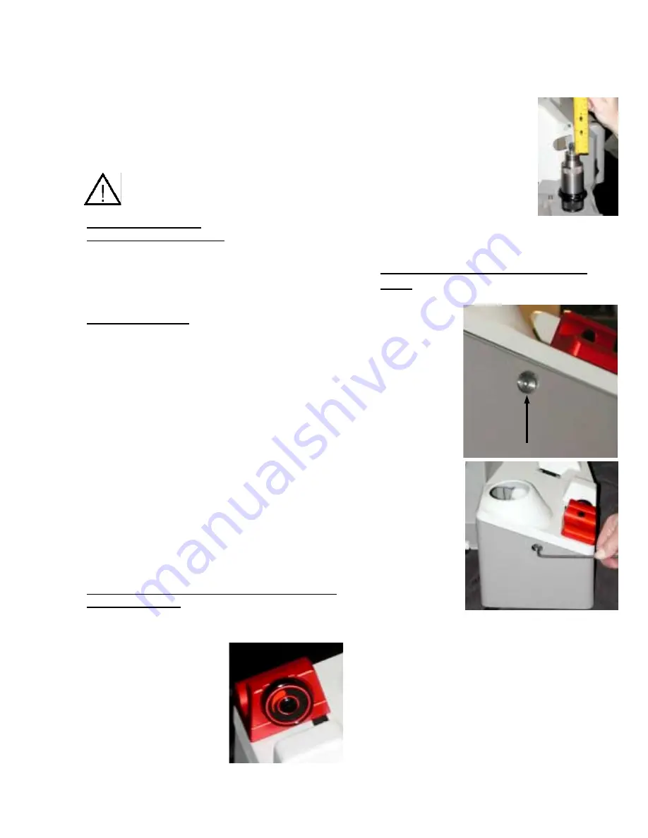
Use a 3/8 HSS standard twist drill, measure the
length of drill before sharpening.
1. Rotate material
removal knob to
maximum take off.
2. Align drill as though
you intend to
sharpen it.
Follow
Alignment steps on
page 11.
3. Once drill is set to
length, aligned and captured in the chuck,
securely remove from alignment port.
4. Measure the amount of drill
protruding from the end of
the chuck to the tip of the
drill.
5. The length of the drill
protruding from the top of
the chuck should
measure .970-.980 (24.63 mm - 24.89
mm)
Calibrating the Material removal
knob
1. Located at
the rear of
the machine
base, you
will find a
small access
hole.
2. Insert a 3/16
Allen wrench
into the
access hole.
3. To advance the pusher shaft cap, reducing
the amount of drill stick out, rotate the
wrench clockwise.
4. To retract the pusher shaft cap, increasing
the amount of drill stick out, rotate the
wrench counterclockwise.
Each ¼ turn will adjust .010 (.25 mm) or one
full turn will adjust .04 (1.0 mm). After adjusting
the pusher shaft assembly, realign the drill and
re-measure the amount of stick out. Repeat the
steps 1-4 until the drill protrudes .970-.980 in
length. (24.63 mm - 24.89 mm)
GENERAL MAINTENANCE
Summary of Contents for XT3000i
Page 1: ......
Page 3: ...2...
Page 9: ...8 XT 3000 Reference Drawing 230V Units Only...
Page 11: ...10...
Page 15: ...14...
Page 25: ...24...
Page 29: ...28...
Page 31: ...30...
Page 33: ...32 Wiring Diagram...
Page 34: ...33 Electrical Diagram...
Page 38: ...37 EXPLODED VIEW MACHINE...
Page 39: ...38 EXPLODED VIEW SHARPENING FIXTURE 118 150...
Page 40: ...39 EXPLODED VIEW ALIGNMENT ASSEMBLY...
Page 43: ...43 Large Drill Attachment...
Page 45: ...45 XY Table Attachment X Y Table No Sub Assemblies Send in for Repair...
Page 46: ...46...
Page 49: ...49 Countersink Attachment...
Page 55: ...55 Step Drill Attachment...


