


Parameter
Description of function
Parameter 5-54 Pulse Filter
Time Constant #29
(Pulse
term. 29),
parameter 5-59 Pulse Filter
Time Constant #33
(Pulse
term. 33),
parameter 6-16 Terminal 53
Filter Time Constant
(analog
term 53),
parameter 6-26 Terminal 54
Filter Time Constant
(analog
term. 54)
If there are oscillations of the current/voltage feedback signal, these oscillations can be dampened with a
low-pass filter. This time constant shows the speed limit of the ripples occurring on the feedback signal.
Example: If the low-pass filter has been set to 0.1 s, the limit speed is 10 RAD/s (the reciprocal of 0.1 s),
corresponding to (10/(2 x π))=1.6 Hz. The example shows that the filter dampens all currents/voltages that
vary by more than 1.6 oscillations per s. The control is only carried out on a feedback signal that varies by
a frequency (speed) of less than 1.6 Hz.
The low-pass filter improves steady-state performance, but selecting too large a filter time deteriorates the
dynamic performance of the process PID control.
Table 16.5 Process Control Parameters
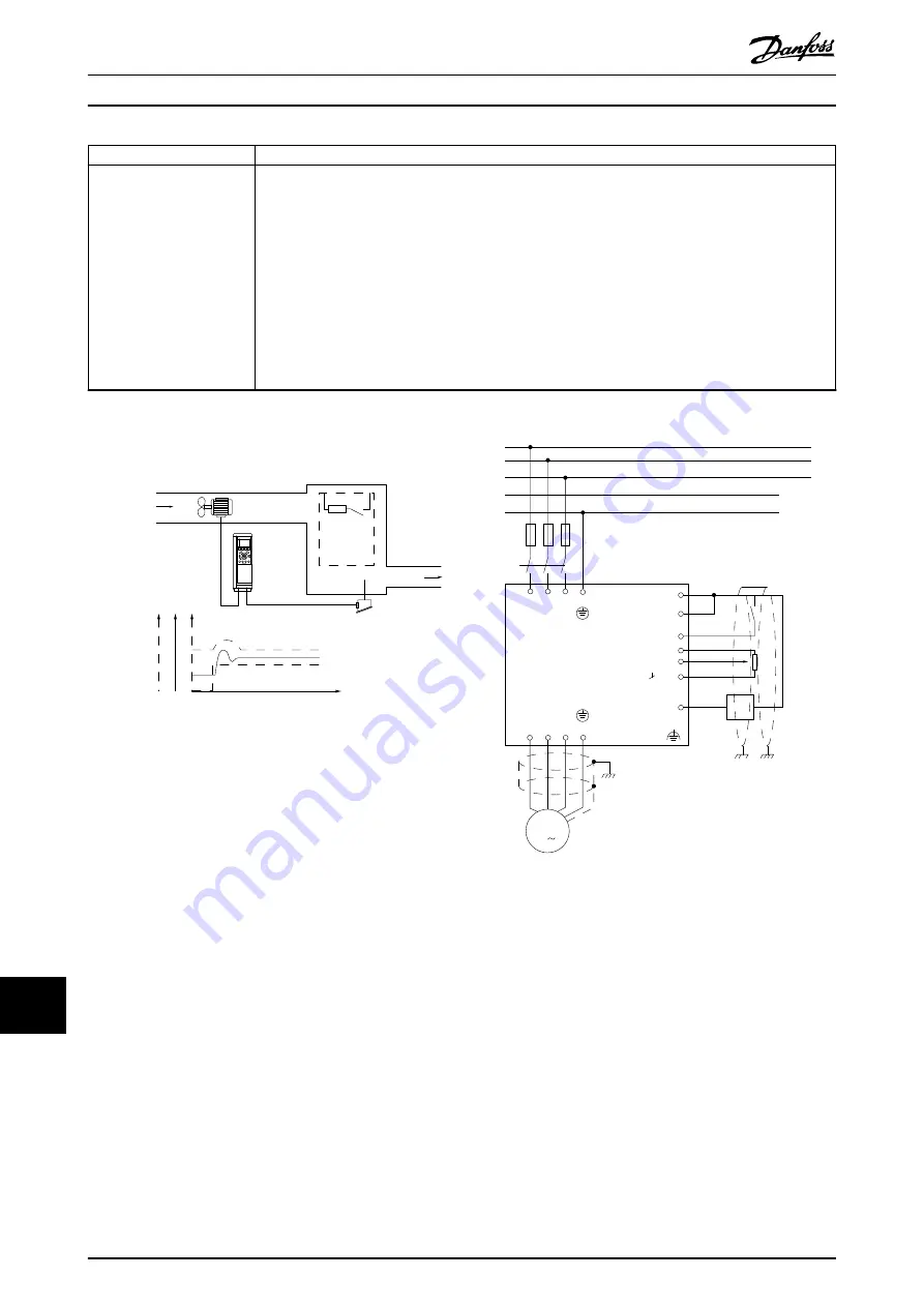
16.2.2 Example of Process PID Control
Temper
atur
e
Fan speed
Temperature
transmitter
Hea
t
Heat
generating
process
Cold air
130BA218.10
100kW
n °C
W
Illustration 16.3 Example of a Process PID Control Used in a
Ventilation System
In this example using a ventilation system, the temperature
must be adjustable from -5
°
C (23
°
F) to 35
°
C (95
°
F) with
a potentiometer of 0–10 V. The process control is used to
keep the set temperature constant.
When the temperature increases, the process PID control
increases the ventilation speed so more airflow is
generated. When the temperature drops, the speed is
reduced. The transmitter used is a temperature sensor with
a working range of -10 (14
°
F) to 40
°
C (104
°
F), 4–20 mA.
Minimum/maximum speed 300/1500 RPM.
Transmitter
96 97
99
98
91 92 93 95
50
12
L1 L2
L1
PE
L3
W PE
V
U
F1
L2
L3
N
PE
130BA175.12
18
53
37
55
54
M
3
5 kΩ
Illustration 16.4 Two-wire Transmitter
The following steps demonstrate how to set up the
process PID control in
.
1.
Start/Stop via switch connected to terminal 18.
2.
Temperature reference via potentiometer (-5 to 35
°
C (23 to 95
°
F), 0–10 V DC) connected to
terminal 53.
3.
Temperature feedback via transmitter (-10 to
40
°
C (14 to 104
°
F), 4–20 mA) connected to
terminal 54. Switch S202 set to ON (current
input).
PID Controls
VLT
®
Parallel Drive Modules
148
Danfoss A/S © 6/2016 All rights reserved.
MG37N102
16
16
Summary of Contents for VLT 380-500 V
Page 2: ......


