background image

X62

X55

X56

X57

X58

X59

2

X60

130BB794.10

1

1

Terminal block 1

2

Terminal block 2

X55

Encoder 2

X56

Encoder 1

X57

Digital inputs

X58

24 V DC supply

X59

Digital outputs

X60

MCO CAN Bus

X62

Debug connections (RS 485)

Illustration 4.3 Location of Terminal Blocks 1 and 2

Use terminal block 1 with bookstyle and terminal block 2
with compact.

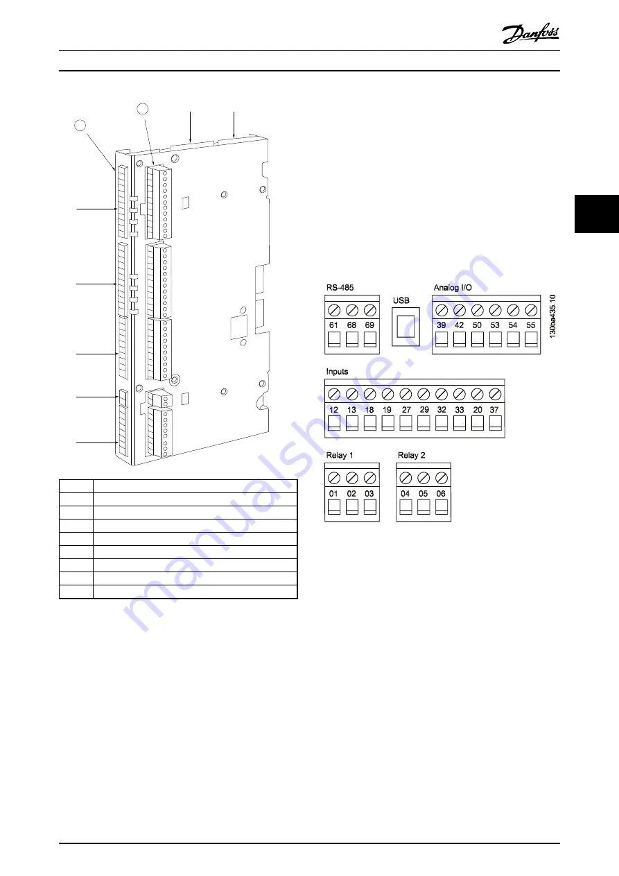
4.2  Frequency Converter Control Card

Terminals

The terminals on the VLT

®

 AutomationDrive control card

are allocated for the MCO 351.

Do not change the following parameters for I/O settings:

Parameters 

5-10

 to 

5-15

 set to 

[0] No operation

(default setting)

Parameters 

3-15

3-16

 and 

3-17

 set to 

[0] No

function

 (default setting)

Parameter 

6-50

 set to

 [52] MCO 0–20 mA

Illustration 4.4 FC 300 Terminals

Technical data on these terminals can be found in the

VLT

®

 AutomationDrive FC 301/FC 302 Design Guide

.

Electrical Installation

Operating Instructions

MG33R302

Danfoss A/S © 04/2014 All rights reserved.

11

4

4

Summary of Contents for MCO 351

Page 1: ...MAKING MODERN LIVING POSSIBLE Operating Instructions Positioning Controller MCO 351 VLT AutomationDrive FC 301 302 www danfoss com drives...

Page 2: ......

Page 3: ...3 4 4 MCO Option Card Terminals 14 4 4 1 X55 Feedback Encoder Input 14 4 4 2 X56 Master Encoder Input Virtual Master Output 14 4 4 3 X57 Digital Input 14 4 4 4 X58 24 V DC Supply 15 4 4 5 X59 Digital...

Page 4: ...ers 40 5 7 4 33 9 MCO Port Settings 40 5 8 MCO Data Readouts 41 5 8 1 34 0 PCD Write Parameters 41 5 8 2 34 2 PCD Read Parameters 41 5 8 3 34 4 Inputs and Outputs 41 5 8 4 34 5 Process Data 41 6 Appli...

Page 5: ...8 3 2 1 Example of Index Positioning via Fieldbus 51 8 3 2 2 Example of Index Positioning via Quick Bus 51 Index 52 Contents Operating Instructions MG33R302 Danfoss A S 04 2014 All rights reserved 3...

Page 6: ...Areas DrivesSo lutions Documentations VLT Technical Documentation htm for listings 1 3 Overview The VLT Positioning Controller MCO 351 is for use with the FC 300 series frequency converters The contro...

Page 7: ...pment containing electrical components can not be disposed of together with domestic waste It must be separately collected with electrical and electronic waste according to local and currently valid l...

Page 8: ...xternal switch a serial bus command an input reference signal from the LCP or LOP via remote operation using MCT 10 software or after a cleared fault condition To prevent unintended motor start Discon...

Page 9: ...regarding PELV 525 690 V At altitudes above 2 km contact Danfoss regarding PELV 2 3 Functional Safety Safe Torque Off is an option To run Safe Torque Off additional wiring for the frequency converter...

Page 10: ...combine it with another option in slot C1 Mounting kit depending on enclosure Order no Bookstyle Enclosure A2 and A3 40 mm for 1 C option 130B7530 A2 and A3 60 mm for C0 C1 option 130B7531 B3 40 mm f...

Page 11: ...Illustration 3 2 Compact Enclosure A5 B except B3 C D E F Mechanical Installation Operating Instructions MG33R302 Danfoss A S 04 2014 All rights reserved 9 3 3...

Page 12: ...ls RS 485 are on the top of the C option cover If these connections are used cut out the plastic parts above the connectors and mount the cable relief 130BA248 11 Illustration 4 1 Location of Encoder...

Page 13: ...trol Card Terminals The terminals on the VLT AutomationDrive control card are allocated for the MCO 351 Do not change the following parameters for I O settings Parameters 5 10 to 5 15 set to 0 No oper...

Page 14: ...Torque Off STO Table 4 1 Digital Inputs Relay 1 Mechanical brake normally open Relay 2 Mechanical brake monitoring normally closed Analog input 53 10 V In Manual jog positive 54 10 V In Manual jog ne...

Page 15: ...D in Safe torque off STO COM A in 10 V OUT Quickstop Manual Jog negative COM A out Touchprobe switch Positive HW limit switch Negative HW limit switch Home reference switch Go to target position Reset...

Page 16: ...Output 130BD653 10 1 2 3 4 5 7 9 11 6 8 10 12 Pin number TTL encoder SSI encoder 1 24 V DC Supply 24 V DC Supply 2 8 V DC Supply 8 V DC Supply 3 5 V DC Supply 5 V DC Supply 4 GND GND 5 A 6 A not 7 B...

Page 17: ...osition reached 3 Error 4 Reference index bit 0 5 Reference index bit 1 6 Reference index bit 2 7 Reference index bit 3 8 Reference index bit 4 Illustration 4 10 X59 Digital Outputs 4 4 6 X62 MCO CAN...

Page 18: ...rake Control 03 NC Normal Closed Relay 02 04 COM Relay 02 Common terminal for Relay 02 05 Brake activated NC Normal Closed Relay 02 is closed to indicate an activated electrome chanical brake It is op...

Page 19: ...sequence and no position or jog operations are carried out Any homing sequence is interrupted by a low state on this input Not used in fieldbus mode 10 Latch new reference position index number Active...

Page 20: ...Connection Examples Example 1 Encoder connected to X55 for positioning loop Since the encoder is mounted directly on the motor shaft the same feedback can be used for the MCO positioning loop and the...

Page 21: ...control loop 130BD830 10 MOTOR X55 X56 Illustration 4 14 Encoders Mounted on the Motor and the Gear Box Example 4 Resolver feedback used MCB 103 option is needed FC speed control loop must be closed M...

Page 22: ...le to specify the target position and velocity If the acceleration and deceleration PCDs are left blank the values for acceleration and deceleration from index 1 are used 4 6 2 Data Layout Control and...

Page 23: ...13 Quick bus type touch probe positive high N A 1 14 Quick bus type touch probe negative high N A 1 15 Teach in via LCP or fieldbus high Back and Cancel on the LCP 1 16 Change sign on quick bus target...

Page 24: ...mit high N A 1 8 Negative hardware limit high N A 2 1 Current index bit 0 4 2 2 Current index bit 1 5 2 3 Current index bit 2 6 2 4 Current index bit 3 7 2 5 Current index bit 4 8 2 6 Current index bi...

Page 25: ...exchange the motor phases 7 Set the parameters for feedback encoder in parameter group 32 0 Encoder 2 parameters and if needed parameters for encoder in parameter group 32 3 Encoder 1 parameters 7a Fo...

Page 26: ...equal to the value set here 19 06 Error Behaviour Option Function 0 Electronic brake This parameter determines the behaviour of the motor after an error is detected The motor ramps down to standstill...

Page 27: ...where a sequence of fast positioning commands is followed by longer standstill periods 19 13 Brake Wear Limit Range Function 0 0 1073741824 UU If a value higher than 0 disabled is set the motor defin...

Page 28: ...ex Trajectory Type Whenever this number is changed the current values of the index parameters are stored in the memory under the previously specified index number After that the values of the index pa...

Page 29: ...as executed previously positioning is relative to the position reached via jogging 2 Touch probe positive Positioning is relative to a touch probe position expected in positive direction 3 Touch probe...

Page 30: ...5 Negative SW limit 6 VLT not running 7 Brake wear limit 8 Quick stop 9 PID error too big 12 Reverse operation 13 Forward operation 92 Encoder hardware error This is a read only parameter It displays...

Page 31: ...is the internal calculation which uses 4 times the number of counts because an incremental encoder returns 4 times more quad counts than its counts An absolute encoder only returns this real resolutio...

Page 32: ...oder SSI clock and data signals will be out of synchronisation if the signal delay caused by the encoder cable is too long The MCO automatically compensates the cable delay when the cable length is kn...

Page 33: ...1 Encoder resolution incremental encoder 500 Spindle gradient 1 revolution of the spindle 5 mm Scaling factor when working with 1 10 mm resolution 5 x 10 50 130BD771 10 25 1 500 25 50 1 qc 1000 1 qc...

Page 34: ...X56 Select the baud rate of the attached encoder Option Function 0 600 Baud 1 1200 Baud 2 2400 Baud 3 4800 Baud 4 9600 Baud 5 19200 Baud 6 38400 Baud 32 35 Absolute Encoder Data Length Range Function...

Page 35: ...to the value of the new encoder Instead the old value is kept and the differences from the new encoder are added This makes it possible to change encoders on the run 32 43 Encoder 1 Control The encod...

Page 36: ...ction output Thus values less than 1000 limit the P share accordingly The bandwidth in which the PID controller should function can be limited For example to avoid the build up of vibration for a syst...

Page 37: ...vation and 32 72 Size of the Control Window Deactivation are used to turn the position control within defined areas control windows on and off Parameter 32 71 Size of the Control Window Activation ind...

Page 38: ...ximum Velocity Encoder Range Function 1500 1 100000 RPM This parameter defines the rated speed of the motor This value is listed in RPM and is needed for the calculation of ramps and actual velocities...

Page 39: ...ccel Max velocity Parameter 32 81 Max jerk Max accel Parameter 32 86 NOTICE Parameters 32 81 Shortest Ramp and 32 86 Acceleration Up for Limited Jerk are time values in milliseconds Calculation sample...

Page 40: ...NOTICE Ramp for Home Motion can never have a higher value than parameter 32 85 Default Acceleration 33 03 Velocity of Home Motion Range Function 10 value to value in parameter 32 83 Velocity Resoluti...

Page 41: ...d otherwise a new reading is taken This parameter indicates the time interval between the measurements NOTICE The time is limited to 10 ms because during that time the application program is blocked a...

Page 42: ...new error is generated Handling of hardware limit switches is the same as software limit switches This means that the error can be cleared and then the motor is enabled to move in the opposite direct...

Page 43: ...tion 34 21 PCD 1 Read from MCO 34 22 PCD 2 Read from MCO 34 23 PCD 3 Read from MCO 34 24 PCD 4 Read from MCO 34 25 PCD 5 Read from MCO 34 26 PCD 6 Read from MCO 34 27 PCD 7 Read from MCO 34 28 PCD 8 R...

Page 44: ...rs 19 09 Automatic Break Control 19 10 Coast Delay 19 11 Brake Delay 19 12 Hold Delay 19 13 Brake Wear Limit If the application is not equipped with an electrome chanical brake these parameters are no...

Page 45: ...switch is an emergency switch for the application Inputs X57 2 Positive hardware limit switch input X57 3 Negative hardware limit switch input Must be kept high to start run the application 6 5 Softwa...

Page 46: ...ng using PCD 6 7 Quick Bus Positioning The MCO 351 is controlled by an overall control system e g a PLC system Parameter 19 04 Control Source must be set to 1 Fieldbus to enable fieldbus operation Ope...

Page 47: ...rameter 19 17 Jog Ramp Time for jogging and parameter 19 26 Index Ramp Down Time for positioning Check PCD 6 Quickbus Target Deceleration If a lower ramp time is required install a brake resistor The...

Page 48: ...be done through an error reset and a negative jog input 54 5 Negative software limit exceeded A motor command has caused the software limit switch to be activated The maximum limit is specified in par...

Page 49: ...erated Position Error may be too low 12 Reverse operation prohibited The motor has been operated in reverse direction while this was not allowed according to the setting in parameter 32 68 Reverse Beh...

Page 50: ...municated via transfer of the position in parallel form or in the form of a telegram in serial form Absolute value encoders also come in 2 versions Single turn encoders supply an absolute position via...

Page 51: ...ouch probe pos I 7 X57 7 PCD 1 7 Touchprobe pos locked PCD 1 5 19 24 19 28 2 Touchprobe Target position Illustration 8 4 Touch Probe Positioning NOTICE A delay in the touch probe sensor makes the targ...

Page 52: ...1 1 1 0007 8 0 1 0 0 0 0008 9 0 1 0 0 1 0009 10 0 1 0 1 0 000A 11 0 1 0 1 1 000B 12 0 1 1 0 0 000C 13 0 1 1 0 1 000D 14 0 1 1 1 0 000E 15 0 1 1 1 1 000F 16 1 0 0 0 0 0010 17 1 0 0 0 1 0011 18 1 0 0 1...

Page 53: ...ositioning via Quick Bus PCD 1 PCD 2 PCD 3 PCD 4 PCD 5 PCD 6 Read Absolute position 65535 UU Velocity 1000 RPM Ramp up down time 500 ms 0 4 8 0 0 0 0 0 F F F F 0 3 E 8 0 1 F 4 0 1 F 4 Move to absolute...

Page 54: ...motion 38 Block direction 24 Brake control 42 Brake delay 25 Brake wear limit 25 C Coast delay 25 Commanded position 41 Control mode 24 Control source 24 Control terminals 10 Conventions 48 D DC Overv...

Page 55: ...N Negative software end limit 39 Negative software end limit active 39 New index 27 O Option card terminals X55 Feedback Encoder Input 14 X56 Master Encoder Input Virtual Master Output 14 X57 Digital...

Page 56: ...er Output 14 X57 Digital Inputs 14 17 X58 24 V DC Supply 15 X59 Digital Outputs 15 17 X62 MCO CAN 15 Time in target window 39 Touch probe delay 24 Touch probe positioning 42 Track error 41 Trajectory...

Page 57: ...Index Operating Instructions MG33R302 Danfoss A S 04 2014 All rights reserved 55...

Page 58: ...lies to products already on order provided that such alterations can be made without subsequential changes being necessary in specifications already agreed All trademarks in this material are property...

Reviews: