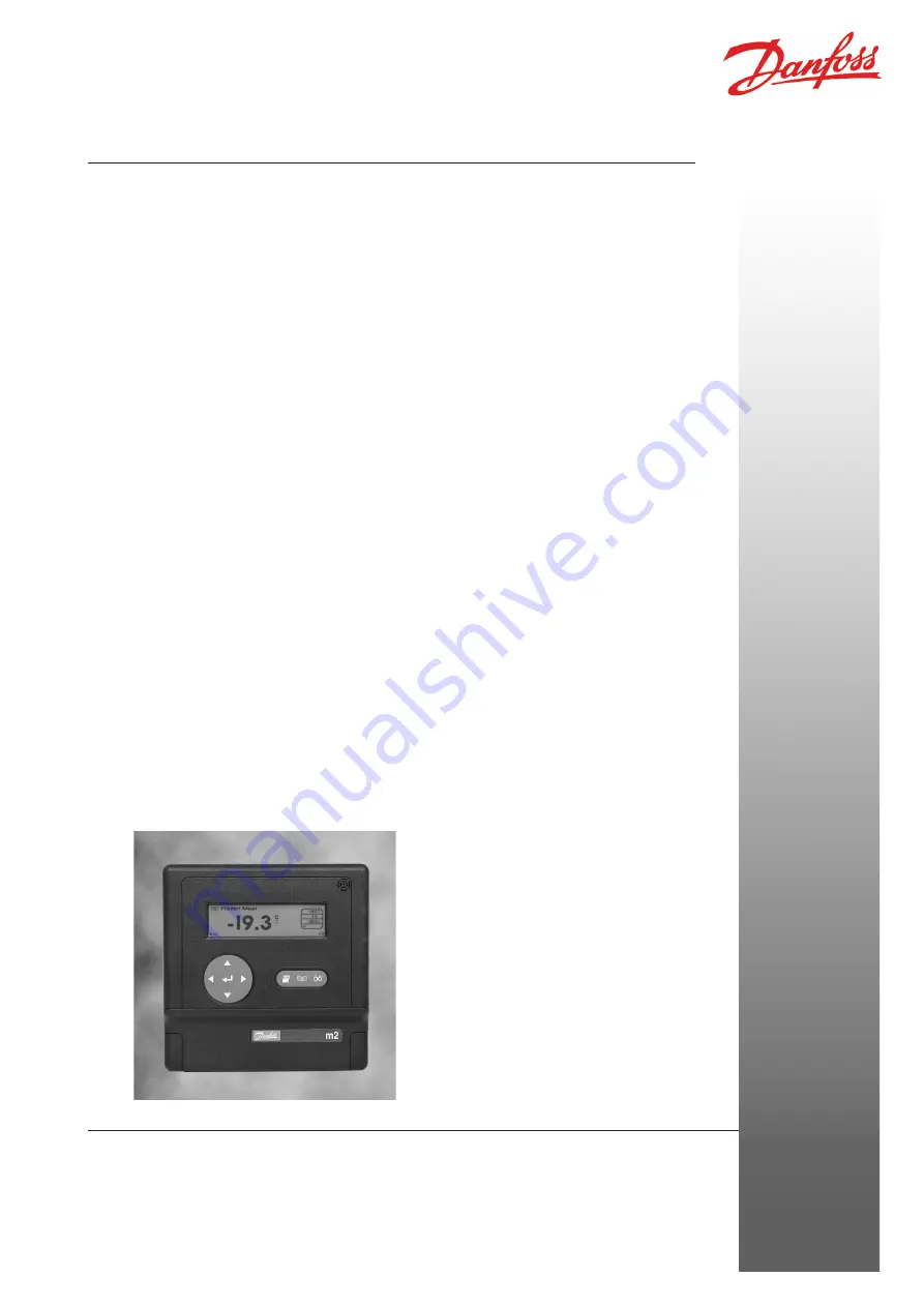
Monitoring, Control and Alarm System
m2
Manual
Refrigeration and Air Conditioning Controls
R E F R I G E R A T I O N A N D A I R C O N D I T I O N I N G
Page 1: ...Monitoring Control and Alarm System m2 Manual Refrigeration and Air Conditioning Controls R E F R I G E R A T I O N A N D A I R C O N D I T I O N I N G...
Page 2: ...Name 16 Setting the Point Type 16 Setting the Units of Measurement 17 Defrost Interlock Point 17 Setting the Alarm Settings 17 Setting the Alarm Action 17 Setting the Log Action 18 Setting the Graph A...
Page 3: ...ition indicated immediately by means of audible and visual alarms Further details on any aspect of the operation of the installation are available via the key pad In addition there is the ability for...
Page 4: ...s case the display backlight will switch off but the display will keep running When an alarm occurs the alarm siren and the red flashing backlight will still operate The backlight will flash red once...
Page 5: ...N h s i n a p S h s i l o P n a i r a g n u H h s i n n i F c i d n a l e c I h s i d e w S h c e z C e r u t a r e p m e t t n e i b m A C 0 7 o t 0 2 t r o p s n a r T C 0 5 o t 0 n o i t a r e p O...
Page 6: ...menu In addition when a character entry field has been selected this key is used to decrement the displayed value in the entry field Secondary Functions Moves through the Point Detail screens moves th...
Page 7: ...s by point when in Point Detail Screen This equipment is safe to operate as long as the instructions in this manual are followed High voltages are present inside the m2 and the front access panel shou...
Page 8: ...l screen will be displayed Note If a point has a local offset applied to it this will be indicated by the presence of the offset icon at the left of the Point Readout window To continuously view the s...
Page 9: ...ed alongside the point type To uninhibit a point repeat the operation If the alarm condition is exceeded on an inhibited point i e Pull down then the animated pull down arrows will be displayed next t...
Page 10: ...remove the graph cursor by pressing again Pressing the key will then take you back to the Point Detail screen When a graph is displayed on the screen pressing the key dumps the graph to a directly co...
Page 11: ...these options press the key When the highlight reaches the bottom of the screen the menu will be scrolled upwards to reveal the extra options Similarly to re display the first two options press the k...
Page 12: ...tion select the Print Menu option from either the Main Menu or by pressing the key on all screens except the Alarm Event List screens In either case the Print Menu screen is displayed Use this option...
Page 13: ...est is displayed Enter your User passcode the default passcode is WOODLEY or the Local passcode Use or keys to cycle through the character list to the required value and the or key to move the cursor...
Page 14: ...scroll through the following options Mode Off Daylight saving switched off Auto US American daylight saving time settings Auto EU European daylight saving time settings Manual Times and offset can be...
Page 15: ...a base character as normal and then add the required accent e g in French if an is required the procedure is to first select e as described above then enter Diacritic mode and select the acute accent...
Page 16: ...of an individual point ensure that the cursor is on the correct point number and press The cursor will move to the Name field Enter the installation name using the or keys to cycle through the charac...
Page 17: ...to cycle through the fields until the Def Int Pt field is highlighted Use the or keys to alter the point number to the defrost input For example if probe 1 is a temperature probe and point 16 is a def...
Page 18: ...ied in the Log Graph Setup screen Manual The graph for the point will be printed on demand only On Set this option to ON if you require a graph for this point to be printed after the time specified in...
Page 19: ...he graph will show This value should be slightly lower than you expect the temperature to drop to If auto scale in the Y axis is selected this value is not used Use the or keys to enter the required v...
Page 20: ...se x 0 2KW x 4 for 1 hour 5 6KW 8 pulses x 0 2KW x 4 for 1 hour 6 4KW Resolution is 0 8 Values could be 0 0 8 1 6 2 4 3 2 4 0 4 8 5 6 6 4 etc With the Peak option the sample rate is 1 minute though th...
Page 21: ...the cursor and to change case When the passcode has been set press then to return to the Setup Menu To set the Inhibit Protection use the key to highlight the Inhibit Protected field then using the or...
Page 22: ...ace when an alarm occurs From the Setup Menu select the Alarm Action Setup option Use the or keys to cycle through the devices and complete the fields for each device as described below RELAY 1 MODEM...
Page 23: ...key is pressed Time Clear the alarm when the time specified under Duration has expired MuteR When in alarm if the Mute key is pressed then the relay will open If after the Duration Time the alarm is s...
Page 24: ...number is always dialled twice unless the busy tone is received MESSAGE7 Indicates that a 7 bit modem is connected with a printer attached 7 bit Even Parity 1 Stop Bit normally used in France MESSAGE...
Page 25: ...There are 4 curve tables available Cf1 Cf2 Cf3 and Cf4 Use the or keys to cycle through the curves until the correct type is displayed The table can have up to 12 break points to define the Curve Tab...
Page 26: ...ss the Input No 1 and C terminals of the unit and set it to the lowest of your selected Output values When you do this you should see a value appear in the To use field This is the Internally Scaled v...
Page 27: ...e character list and the or key to move the cursor left or right respectively Note Refer to your modem handbook for details of the valid modem commands and answer codes When you have finished or to ab...
Page 28: ...an be used to control the modem power The Relay is rated at 24V 1A max so the low voltage power after the mains transformer must be switched Mains voltage MUST NOT be connected to this relay Modem to...
Page 29: ...d only by a qualified service personnel and should ensure that replacement parts match the original safety characteristics CAUTION This unit is fitted with rechargeable batteries use only manufacturer...
Page 30: ...iously described except for the following Set this field to either RTD for temperature monitoring or 420 for 4 20mA inputs With the Type field highlighted press the key to display the second point set...
Page 31: ...exceeded A wave Indicates the set point for the EKC controller Indicates the lower alarm limit setting When the part of the symbol is scrolling it indicates that the lower alarm limit has been exceed...
Page 32: ...l thermostat EKC 301 EKC 202 version A B C D EKC 331 EKC 331T EKC 531D1 version 1 36 application 1 1 361 AK PC 530 version 1 36 application 1 1 361 Do not use the same address for several EKC controll...
Page 33: ...The alarm limits for the controller will be used Other settings are those normally used for m2 Next menu Press and hold down the Enter key until the second Point Setup screen is displayed or press th...
Page 34: ...12 13 14 15 Action number for use in setting the trigger 1 2 3 4 5 6 7 8 Function Relay 1 Trigger settings 1 1 1 Relay 2 Siren 1 1 1 1 1 1 1 1 Lamp 1 1 1 1 1 1 1 1 Flash 1 1 1 1 1 1 1 1 Dial O 1 1 D D...
Page 35: ...oss 10 2007 35 Example The siren is ON when action 1 2 9 or 10 occurs Relay 1 is ON when action 2 7 10 or 15 occurs A call is made to the following number when action 1 2 3 8 9 10 or 11 occurs However...
Page 36: ...are property of the respecitve companies Danfoss and Danfoss logotype are trademarks of Danfoss A S All rights reserved List of Literature Manual RS 8A N Provides full instructions on how to operate t...