background image

80 


Spyder3 GigE Vision SG-14 Monochrome Cameras User’s Manual 

03-032-20123-01 


Teledyne DALSA 

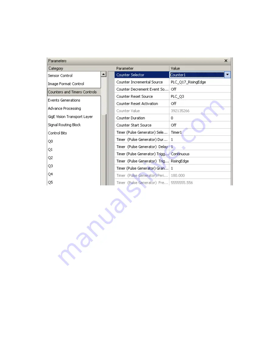
Counter 

The cou nter m aintains a cou nt valu e that can be increased , d ecreased , or cleared  based  on inp u t signals. 
The cou nter ou tp u ts tw o signals (w hich are inp u ts to the GPIO LUT).  


Counter Incremental Source 

Specifies how the input for incrementing the count is hand led . The counter’s up event uses the Q17 label 
in the LUT. It can be one of the follow ing settings: 


Disabled  


On the rising ed ge 


On the falling ed ge 


On both ed ges 


On the high level 


On the low  level 

Counter Decrement Event Source 

Sam e as above bu t for the d ow n event, bu t u ses the Q16 label in the GPIO LUT.  

Counter Reset Activation 

Sam e as above bu t for the clear event. The clear event inp u t of the cou nter d oes not have a p red efined  
label on the GPIO LUT. 

Counter Reset Source 

Ind icates w hich label from  the GPIO LUT that w ill be associated  w ith the clear event inp u t of the cou nter. 
Make su re you  select an inp u t label that is not being u sed  for its d efau lt behavior. The p ossible valu es a re: 
Q3, Q7, Q8, Q9, Q10, Q11, Q16, and  Q17. 

Summary of Contents for GiGE Vision Spyder3 SG-14

Page 1: ...Spyder3 SG 14 Monochrom Camera User s Manual 31 May 2013 03 032 20123 01 www teledynedalsa com ...

Page 2: ...and services For more information visit Teledyne DALSA s website at www teledynedalsa com Support For further information not included in this manual or for information on Teledyne DALSA s extensive line of image sensing products please contact North America 605 McMurray Rd Waterloo ON N2V 2E9 Canada Tel 519 886 6000 Fax 519 886 8023 www teledynedalsa com sales americas teledynedalsa com support t...

Page 3: ...6 5 Operate the Camera 16 Step 1 Ethernet Network Card Install and Configure 17 Install Network Card 17 Configure Network Card 17 Step 2 Connect Power Ethernet and Trigger Cables 20 Power Connector 20 Ethernet Connector and Ethernet LED 21 Status LED 21 GPIO Connector External Input 22 GPIO Isolation 22 GPIO Configuration 22 TTL Inputs and Outputs 23 Step 3 Establish Communication with the Camera ...

Page 4: ..._____________________________55 Gate Dark Current Clear 55 Auto Mode srm 0 55 Immediate read out mode default srm 2 56 Gate dark current clear mode always on srm 1 56 Setting the Readout Mode 57 Appendix B Sensitivity Mode ________________________________________________________________________58 Sensitivity Mode and Pixel Readout 58 Appendix C GPIO Control ________________________________________...

Page 5: ...90 How the Lookup Table Works 93 Appendix D EMC Declaration________________________________________________________________________94 Appendix E Setting up the FVAL ______________________________________________________________________95 Examples Setting the FVAL 99 Revision History _________________________________________________________________________________102 Index _________________________...

Page 6: ...es Broadband responsivity up to 408 16 DN nJ cm2 10dB gain 1024 2048 or 4096 x 2 pixels 14 µm x 14 µm 1k and 2k and 10 µm x 10 µm 4k pixel pitch 100 fill factor High or low speed 40 or 80 MHz Up to 68 KHz line rates Dynamic range up to 1400 1 Data transmission up to 100 meters RoHS and CE compliant GenICam compliant Programmable gain offset exposure time and line rate trigger mode test pattern out...

Page 7: ...ded QuickCam Version 2 0 Compliant Pleora Technologies Inc s Coyote Compliant Third party software E g CVB and NI Compatible Drivers need to be provided by the third party Camera Performance Specifications Table 3 Camera Performance Specifications Feature Specification 1k 2k 4k Imager Format dual line scan dual line scan dual line scan Resolution 1024 x 2 pixels 2048 x 2 pixels 4096 x 2 pixels Pix...

Page 8: ...erating Specifications Specifications Unit 10 dB 0 dB 10 dB Min Typ Max Min Typ Max Min Typ Max Broadband responsivity DN nJ cm 1k and 2k Dual line 652 8 2064 6528 1k and 2k Single line 326 4 1032 3264 4k Dual line 431 1363 4k Single line 216 682 Random noise rms DN 1k and 2k 3 6 5 9 2 20 5 30 65 4k 10 24 Dynamic range DN DN 1k and 2k Dual line 500 1 1400 1 203 1 324 1 59 1 108 1 1k and 2k Single ...

Page 9: ...752 4k Dual and Single Corrected local DN p p 237 237 Corrected global DN p p 237 237 Uncorrected local 9 5 9 5 Uncorrected global 20 20 SEE calculated nJ cm 1k and 2k Dual line 6 35 1 92 0 61 1k and 2k Single line 12 2 4 0 1 2 4k Dual line 9 2 2 9 4k Single line 18 0 5 7 NEE calculated pJ cm Dual line 4 6 4 5 4 6 Single line 9 2 9 3 9 2 4k Dual line 7 0 8 1 4k Single line 14 0 16 1 Saturation out...

Page 10: ...gen 3250k with 750 nm high pass filter installed Ambient test temperature 25 C Unless specified all values are referenced at 12 bit Exposure mode disabled Unless specified dual line mode Note PRNU measured at 50 SAT Certifications Table 5 EMC Compliance Standards Compliance The CE Mark FCC Part 15 and Industry Canada ICES 003 Evaluation of the Teledyne DALSA Spyder GigE SG 14 cameras meet the foll...

Page 11: ...ty Figure 1 Spyder3 GigE Vision 1k and 2k Responsivity Figure 2 Spyder3 GigE Vision 4k Responsivity Spectral Responsivity 0 dB Gain 0 200 400 600 800 1000 1200 1400 1600 1800 2000 400 500 600 700 800 900 1000 1100 Wavelength nm Low Sensitivity Mode Hi Sensitivity Mode 12 b its D N nJ cm Resp on sivity 2 ...

Page 12: ...12 Spyder3 GigE Vision SG 14 Monochrome Cameras User s Manual 03 032 20123 01 Teledyne DALSA Mechanicals Figure 3 Spyder3 1k and 2k GigE Vision Mechanical ...

Page 13: ...Spyder3 GigE Vision SG 14 Monochrome Cameras User s Manual 13 Teledyne DALSA 03 032 20123 01 Figure 4 Spyder3 4k GigE Vision Mechanical ...

Page 14: ...ting Example Image Sensor The camera uses Teledyne DALSA s dual line scan sensor The camera can be configured to read out in either high or low sensitivity mode tall pixel mode and forward or reverse shift direction Tap 2 Tap 1 CCD Readout Shift Register CCD Readout Shift Register NPixels NPixels N 1024 2048 4096 Pixel 1 1 Figure 6 2 Tap Sensor Block Diagram Tap 1 CCDReadout Shift Register CCDRead...

Page 15: ...er a range of functions and performance grades so care must be taken to choose the right switch for a particular application Setup Steps Overview Take the following steps in order to setup and run your camera system They are described briefly below and in more detail in the following sections 1 Install and Configure Ethernet Network Card If your host computer does not have a Gigabit network adapte...

Page 16: ... to the camera 3 Establish communicating with the camera Start the GUI and establish communication with the camera 4 Check camera LED settings and test pattern Ensure that the camera is operating properly by checking the LED the current settings and by acquiring a test pattern 5 Operate the Camera At this point you will be ready to operate the camera in order to acquire and retrieve images set cam...

Page 17: ...hown here uses the Windows XP operating system as the host platform The camera communicates using the Ethernet connection and employs the static IP address 192 168 5 100 default A static address ensures the fastest operation Alternatively you can use a dynamic IP address To configure the network card from the host PC 1 In the Start menu under Control Panel select Network Connections and configure ...

Page 18: ...y the camera In the example below the address 192 168 5 50 is used Alternatively select Obtain an IP address automatically to use a dynamic address 6 Set subnet to 255 255 255 0 and click on OK Figure 9 IP Address 7 Click OK to save settings 8 Click on Configure button and select Advanced tab 9 Enable Jumbo Frames to greater than 9000 bytes If your NIC does not support jumbo packets the image tran...

Page 19: ...Spyder3 GigE Vision SG 14 Monochrome Cameras User s Manual 19 Teledyne DALSA 03 032 20123 01 Figure 10 Jumbo Frames 10 Click OK to save settings ...

Page 20: ...ormance of the camera Figure 11 Input and Output trigger and Power Connectors Power Connector WARNING It is extremely important that you apply the appropriate voltages to your camera Incorrect voltages may damage the camera Input voltage requirement 12 V to 15 V DC The camera requires a single 6 pin Hirose connector with a single voltage input 12 VDC to 15 VDC for power The camera meets all perfor...

Page 21: ... Steady ON indicates that an Ethernet connection is successfully established at 1Gbps Data Transmission LED Steady ON indicates that the camera is ready for data transmission Flashing indicates that the camera is transmitting or receiving data EMC Compliance In order to achieve EMC compliance the Spyder3 camera requires the use of shielded CAT5e or CAT6 Ethernet cables Status LED The camera is equ...

Page 22: ...7 INPUT_2 LVDS negative Direction 8 INPUT_3 TTL auxiliary input 9 OUTPUT_3 TTL auxiliary output 10 OUTPUT_2 LVDS TTL auxiliary output 11 OUTPUT_0 LVDS TTL auxiliary output 12 OUTPUT_0 LVDS negative 13 OUTPUT_1 LVDS TTL auxiliary output 14 OUTPUT_1 LVDS negative 15 OUTPUT_2 LVDS negative A schematic of the TTL input circuitry is shown in Figure 13 TTL Input Schematic The input signals are fed into ...

Page 23: ...A Input voltage maximum of low 0 66 V minimum of high 2 6 V TTL inputs are maximum 5 V and 3 3 V logic tolerant Figure 14 TTL Output Schematic Termination 100 Ω series Output current sink 50 mA source 50 mA Output voltage maximum of low 0 55 V 32mA minimum of high 3 8 V 32mA LVDS Inputs and Outputs LVDS compliant Figure 15 LVDS Input Figure 16Figure 17 LVDS Output 1000 3 3V 3 3V TTL 100 ESD Protec...

Page 24: ...during the software installation 2 CamExpert will search for installed Sapera devices In the Devices list area on the left side the connected Spyder camera will be shown 3 Select the Spyder camera device by clicking on the camera user defined name By default the camera is identified by its serial number Check LED Status If the camera is operating correctly at this point the diagnostic LED will fla...

Page 25: ...ter files on the host system ccf An important component of CamExpert is its live acquisition display window which allows immedia te verification of timing or control parameters without the need to run a separate acquisition program For context sensitive help click on the button then click on a camera configuration parameter A short description of the configuration parameter will be shown in a popu...

Page 26: ...that device Optionally select a camera file included with the Sapera installation or saved by the user Parameters pane Allows viewing or changing all acquisition parameters supported by the acquisition device CamExpert displays parameters only if those parameters are supported by the installed device This avoids confusion by eliminating parameter choices when th ey do not apply to the hardware in ...

Page 27: ... the I O control parameters set to Trigger Enabled Software Trigger type click to send a single software trigger command CamExpert display controls these do not modify the frame buffer data Stretch image to fit set image display to original size or zoom the image to any size and ratio Histogram Profile tool Select to view a histogram or line column profile during live acquisition Output Message pa...

Page 28: ... that can be used to confirm camera Ethernet connections without the need for a camera lens or proper lighting The test patterns are useful for verifying camera timing and connections and to aid in system trouble shooting Using CamExpert select Image Format Control Test Image Selector and choose one of the available test images Select live grab to see the pattern output The following test patterns...

Page 29: ...camera functions and save settings Camera Operation Factory Settings The camera ships and powers up for the first time with the following factory settings High sensitivity mode Forward CCD shift direction 8 bit 2 tap No binning Exposure mode internal sync maximum exposure time 5 000 Hz line rate Factory calibrated analog gain and offset Factory calibrated FPN and PRNU coefficients ...

Page 30: ... is 15 C greater than the temperature at the front plate The temperature should not exceed 80 C Read Camera input voltage Click to read the voltage from the camera Verify Temperature and Voltage To determine the voltage and temperature at the camera use the Read Voltage and Temperature feature found in the Camera Information set The temperature returned is the internal chip case temperature in deg...

Page 31: ...ets contain feature settings previously saved by the user User Set Load Load GigE Configuration Load the set specified by User Set Selector to the camera and make it the active current set User Set Save Save Configuration Save the current set as selected user set Description of the Camera Settings The camera operates in one of three settings 1 Current session 2 User setting 3 Factory setting Defau...

Page 32: ...restore By default the user settings are shipped with the same settings as the factory set The command User Set Save saves the current settings to non volatile memory as a User Set The camera automatically restores the last saved user settings when it resets and or powers up To restore the last saved user settings select the User Set parameter you want to restore and then select the User Set Load ...

Page 33: ...ll display 1 if it cannot detect a signal This feature is available when the Line Trigger Mode is set o ON and Sensor Direction Control is set to External The three trigger modes are described here Free running trigger disabled The camera free running mode has a programmable internal timer for line rate and a programmable exposure period Line rate is 0 1 fps to the maximum supported by the sensor ...

Page 34: ...in Typ Max Notes tLine_Period μs 27 78 1000 1K 1 Tap 14 71 1000 1K 2 Tap 54 1 1000 2K 1 Tap 27 78 1000 2K 2 Tap 54 1 1000 4k 2 Tap twSync ns 100 twSYNC_INT ns 100 3000 For exposure mode 4 this value needs to be 3000ns other wise 100ns tPR ns 0 twPR_LOW ns 3000 twPR_HIGH ns 3000 tPR_INT ns 3000 Table 9 tReadout Values tREADOUT Sensor Size Taps Readout Time 1024 1 25600ns 1024 2 12800ns 2048 1 51200...

Page 35: ...on mode of the Exposure or shutter Off Timed Trigger Width If Off is selected then the camera uses the maximum time according to its line rate Line Trigger Group Line Trigger Mode The state of the line trigger If the trigger is off then the line trigger is internally generated Otherwise the line trigger is caused by an external signal Modes Off or On Set the Exposure Mode Sets the camera s exposur...

Page 36: ...d LineTriggerMode On External Line rate is set by the period of the external trigger pulses The falling edge of the external trigger marks the beginning of the exposure Example 2 Line Rate is set by External Trigger Pulses Mode C Smart EXSYNC External Line Rate and Exposure Time ExposureMode TriggerWidth and LineTriggerMode On External In this mode EXSYNC sets both the line period and the exposure...

Page 37: ...ra is operating in Internal Imaging Mode Trigger Mode off GigE Vision Input Controls Sensor Control Parameter Description Line Rate Hz Camera line rate in Hz 300 Hz min 68000 Hz max Only available when the camera is in Internal Mode trigger is disabled Trigger Mode off Line rates are in the following configurations 1k 1 tap 300 36000 Hz 1k 2 tap 300 68000 Hz 2k 1 tap 300 18500 Hz 2k 2 tap 300 3600...

Page 38: ... the start of an Acquisition of a Frame It can also be used to control the exposure duration at the beginning of a frame Parameter Description Trigger Overlap Specify the type of trigger overlap permitted with the previous frame This defines when a valid trigger will be accepted or latched for a new frame Trigger Delay Raw Specifies the delay in microseconds μs to apply after the trigger reception...

Page 39: ...en Line Trigger Mode in set to On Line Trigger Activation Specifies what type of signal i e high or low causes a line trigger if Line Trigger Mode is On External Line Trigger Frequency Reads the external line trigger frequency NOTE The camera cannot detect frequency less than 5 Hz and will display 1 if it cannot detect a signal This featuer is available when the Line Trigger Mode is se to ON and S...

Page 40: ... at PLC_Q1 Line2 outputs signals at PLC_Q2 Line3 outputs signals at PLC_Q3 Output Format This feature returns or sets if possible the current electrical format of the selected physical output Line No Connect TTL or LVDS Gain Black Level and Background The cameras provide gain and black level adjustments in the digital domain for the sensor The gain and black level controls can make small compensat...

Page 41: ...ra Model 1K 2K Cameras 4K Cameras Analog Gain 10 dB to 10 dB Calibrated 0 dB default Not available in GigE Calibrated 10 dB default Digital Gain 4096 0 dB default to 65535 20 dB 4096 0 dB 12953 10 dB default Image Size To set the height of the image and therefore the number of lines to scan and transmit use the parameters grouped under the Image Format Control set GigE Vision Input Controls Image ...

Page 42: ...g speeds in low light It can also allow for reduced lighting levels The available modes are Low High and Tall More description and examples of the sensititivy mode can be found in the App endix GigE Vision Input Controls Image Format Control Parameter Description Sensitivity Mode High Low Tall Sensor Direction Control Found in the I O Control Direction Control set of features Note This feature is ...

Page 43: ... the external signal that controls the sensor shift direction This feature is available only when sensorScanDirection is set to External Sensor Shift Direction When in high sensitivity mode you can select either forward or reverse CCD shift direction Selectable direction accommodates object direction change on a web and allows you to mount the camera upside down Figure 23 Object Movement and Camer...

Page 44: ...essing times and require greater signal collection The Binning Horizontal feature in the Image Format Control set represents the number of horizontal pixels that will be combined added together GigE Vision Input Controls Image Format Control Parameter Description Binning Horizontal This feature represents the number of horizontal photo sensitive cells that must be combined added together Update th...

Page 45: ...er The digital processing chain contains the FPN correction the PRNU correction the background subtract and the digital gain and offset All of these elements are user programmable and most are members of the Analog Controls and Data Processing sets Figure 24 Signal Processing Chain Analog Processing Digital Processing analog video analog gain analog offset FPN coefficients digital offset PRNU coef...

Page 46: ... is used to subtract away individual pixel dark current 2 The digital offset Digital Offset DN parameter enables the subtraction of the artificial A D offset the analog offset so that application of the PRNU coefficient does not result in artifacts at low light levels due to the offset value You may want to set the Digital Offset DN value if you are not using FPN correction but want to perform PRN...

Page 47: ...l strength before the A D conversion It is used to take advantage of the full dynamic range of the A D converter The Analog Controls Gain Selector feature selects the tap to apply the gain value to The Gain dB feature is then used to apply a gain value in a range from 10 dB to 10 dB Note This feature is not available on the 4k camera model Calibrate Camera Gain Instead of manually setting the anal...

Page 48: ... Outside of specification Analog gain set outside 10 dB 3 Clipped to min Analog gain set 0 which may be below 10 dB or System gain set to 0 4 Clipped to max Analog gain set to 1023 which may be above 10 dB or System gain set to 65 535 16x 5 Timeout FPGA did not return new end of line statistics Notes This function requires constant light input while executing If very few tap pixels are within the ...

Page 49: ...to change the gain on all taps by the same amount Calibrate the Camera to Remove Non Uniformity Flat Field Correction Calibration Overview When a camera images a uniformly lit field ideally all of the pixels will have the same gray value However in practice this is rarely the case see example below as a number of factors can contribute to gray scale non uniformity in an image Lighting non uniformi...

Page 50: ...bration is performed next to determine the multiplication factors required to bring each pixel to the required value target for flat white output Video output is set slightly above the brightest pixel depending on offset subtracted Flat Field Correction Restrictions It is important to do the FPN correction first Results of the FPN correction are used in the PRNU procedure We recommend that you rep...

Page 51: ...e Correction results are valid only for the current analog gain and offset values If you change these values it is recommended that you recalculate your coefficients Digital Signal Processing To optimize camera performance digital signal processing should be completed after any analog adjustments The FPN and PRNU calibration parameters are available as members of the Advanced Processing set and ar...

Page 52: ... light from entering the camera i e cover the lens WARNING This command can take up to 3 seconds Please adjust the GUI s timeout values Target to Calibrate PRNU The target value for the PRNU calibration algorithm PRNU Calibrate Calibrate PRNU coefficients Ideally FPN calibration should be done before the PRNU calibration To calibration PRNU the direction must not be External Always set proper targ...

Page 53: ...causes the Background Subtract Raw value to be set to 0 no background subtraction and the Digital Gain Raw value to 4096 unity digital gain The pixel coefficients are disabled Pixel Set Load 0 during the algorithm execution but returned to the state they were prior to command execution 1 Remove the lens cap and prepare a white uniform target 2 Adjust the line rate so that the average output is abo...

Page 54: ...orming flat field correction if you want to improve your image in a low contrast scene It is useful for systems that process 8 bit data but want to take adv antage of the camera s 12 bit digital processing chain You should try to make your darkest pixel in the scene equal to zero Background Subtract Selector to select taps and Background Subtract DN to subtract a value in a range from 0 to 4095 DN...

Page 55: ...selected by the srm command are Auto On or Off Note When auto clear is ON in the HS dual line mode the leading TDI stage is transferred separately and stored in the camera memory TDI summing is recreated by adding stored data to the trailing TDI stage in the camera processing chain Due to digital summing dark noise will increase by 2 A digital add will not increase dominant shot noise Auto Mode sr...

Page 56: ...cies or 10 Hz where dark current is significant A small DN step will be visible in the image where the watchdog turns on and off The watchdog operates on the single threshold If sync frequency is not in the sharp transition watchdog may cause corrupted lines crossing the threshold Gate dark current clear mode always on srm 1 In this mode the gate dark current will be cleared continuously After the...

Page 57: ...ear dark current Default mode The vertical transfer gates collect dark current during the line period This collected current is added to the pixel charge If the user is in sem 2 or 7 and srm 2 with ssf at 45 of the maximum 30 in HS mode and then srm 1 is selected the following warning will be displayed but the ssf value will not be changed Warning 09 Internal line rate inconsistent with readout ti...

Page 58: ...es using both sensors creating a 28µm x 14µm pixel High sensitivity mode permits much greater scanning speeds in low light It can also allow for reduced lighting levels The sensitivity mode is software controlled through GigE compliant interface using the Sensitivity Mode feature part of the Image Format Controls set Figure 28 High Sensitivity Mode In high sensitivity mode the camera uses either a...

Page 59: ...Pixel Mode In tall pixel mode the camera uses a 28 µm x 14 µm pixel 1k and 2k or a 20 µm x 10 µm pixel 4k model and captures an image two times taller than in high or low sensitivity modes resulting in a taller image CCD Readout Shift Register CCD Readout Shift Register Sensor 2 14µm x 14µm OR 10µm x 10µm Sensor 1 14µm x 14µm OR 10µm x 10µm 14 10µm Pixel Detail Pixel Detail 14 10µm CCD Readout Shi...

Page 60: ...already been performed for the Beginner level scenarios described below 3 If you want to use applications other than those provided in the Beginner level examples you can use the LUT programming language to map the GPIO Input Configuration to the GPIO Output Configuration in the Guru level Note the screenshots presented in this section are from the CamExpert GUI If you are using a different GUI th...

Page 61: ... 13 OUTPUT_1 LVDS TTL auxiliary output 14 OUTPUT_1 LVDS negative 15 OUTPUT_2 LVDS negative Table 15 GPIO Signals Configure GPIO Signal Levels Before using any external triggers the input lines must be set to a proper signal level either TTL transistor transistor logic or LVDS low voltage differential signaling The Spyder 3 GigE cameras hardwire 3 input lines that require signal level selection Lin...

Page 62: ...art with free running mode Examples Setting the Camera Modes Free Run Mode Internal Line Trigger Internal Direction Control Internal frame trigger In the Line Trigger Function Group set the parameter Line Trigger Mode value to Off Figure 33 Line Trigger In the Direction Control Group set the parameter Sensor Scan Direction to Forward or Reverse depending on your application Figure 34 Scan Directio...

Page 63: ...edyne DALSA 03 032 20123 01 In the Rotary Encoder Group set the value to False Figure 35 Rotary Encoder Group In the Start Mode set the Frame Start Trigger value Off Figure 36 Start Mode In the Active Mode set the Frame Active Trigger value Off Figure 37 Active Mode ...

Page 64: ...ternal Line Trigger External Direction Control Internal frame trigger Set the Frame Start Trigger and Frame Active Trigger values to off as described above Set the Line Trigger Mode value to Off and the Exposure Mode Exposure Time and Line Rate as above In the Direction Control Group set the Sensor Scan Direction to External Set the Input Direction Signal to Line 2 as described at the start to thi...

Page 65: ...ine 0 as described at the start to this section Verify the line frequency value by clicking the Read External Line Frequency parameter in the Line Trigger Function Group as shown in the figure above If the rescaler is needed set the rescaler as shown in the following figure Figure 41 Rescaler If the rescaler is enabled the external line frequency will be modified using the Trigger Multiplier and T...

Page 66: ...In the Line Trigger Function Group Set the Line Trigger Mode value to On Set Rotary Encoder Module to True Figure 42 Rotary Encoder Module Rescale the line trigger signal The rotary encoder has its own built in rescaler Setting Rotary Encoder Multiply Factor to 0 produces an output frequency that is 4 times the rotary encoder output To set the output to be the same as rotary encoder output set the...

Page 67: ...ary Encoder Direction Phase In some situations it is desirable to only respond to one direction either forward or reverse yEnable the Encoder Backlash Control function and the Scan Direction to desired direction Figure 45 Encoder Backash Control If the Backlash Control is disabled the camera will respond to both directions This may cause image artefacts when the direction changes To avoid this inc...

Page 68: ...gure 46 Rotary Encoder Debounce Factor Figure 47 Shaft Encoder Module External Frame Trigger Frame Start Trigger mode In the Frame Trigger Function Group set the Device Scan Type to Linescan Figure 48 Device Scan Type In the Active Mode group ensure that the Frame Active Trigger Mode value is Off ...

Page 69: ...he frame trigger goes high the software grabs a predefined number of lines as defined in width and height in Image Format Control For a software trigger toggle Frame software trigger from a False value to a True value or from True to False depending on the Frame Active Trigger Mode Enable the delayer in the Start Mode group set the Frame Start Delay value to True Figure 51 Frame Start Delay In the...

Page 70: ...igger Frame Active Trigger mode In the Start Mode group Make sure Frame Start Trigger Mode is Off Figure 53 Frame Start Trigger Mode Off In the Frame Trigger Function Group Set the Device Scan type to Areascan Figure 54 Frame Trigger Source In the Active Mode group set the Frame Active Trigger Mode value to ON Figure 55 Frame Trigger Mode On ...

Page 71: ...int you can enable frame delayer as well Figure 56 Frame Active Delay Outputs Outputs are used to control external devices and monitor internal signals Step 1 Select the output line Step 2 Set the Signal Routing Block parameter Refer to section PLC Input Signal Routing Block for more detail about PLC settings Important Note Signals PLC_10 to PLC_15 should not be changed unless you are very experie...

Page 72: ...tor The signal to output can be selected from the Signal Routing Block parameters For example the following figures will output line 0 Please note that the frame valid PLC_A4 is always high since Spyder3 is a line scan camera Figure 58 Signal Routing Block Figure 59 Signal Q0 linked to the value of parameter PLC_10 ...

Page 73: ...lowing instructions are based on the default settings of the camera Cameras are shipped from the factory in a default setting Default settings are restored by loading the factory default see the figure below NOTE loading the factory default will take 10 seconds or more to complete If you are not using CamExpert it is recommended that you set your GUI timeout values to maximum setting If you do not...

Page 74: ...32 20123 01 Teledyne DALSA PLC_Q7 is fed to a rescaler input So the rescaler will rescale line trigger signals PLC_Q16 is set to Line1 which is frame trigger PLC_Q16 is fed into delayer so the frame trigger signal can be delayed PLC_Q6 is direction and is fed by line2 ...

Page 75: ...0123 01 PLC_Q4_Variable0 can be PLC_I0 or PLC_I3 depending on whether or not the rescaler is enabled PLC_Q12_Variable0 can be PLC_I1 or PLC_I4 depend ing on whether or not the delayer is enabled PLC_Q14_Variable0 can be PLC_I1 or PLC_I4 depending on whether or not the delayer is enabled ...

Page 76: ...ntil the next trigger occurs If a trigger occurs while pulse generator is already handling a previous trigger the new trigger is ignored In periodic mode the trigger continuously generates a signal that is based on the configured delay and width The period of the pulse is therefore the delay time plus the width time Figure 60 Pulse Generator Pulse Generator 0 to 3 Selects which pulse generator to ...

Page 77: ...r This value is computed every time the delay width or granularity is modified and is available regardless of the periodic mode Pulse Generator Timing Positive Pulse Generated from a Rising Edge Trigger Trigger Pulse_Out pulse_delay pulse_width Negative Pulse Generated from a Level High Trigger Trigger Pulse_Out pulse_delay pulse_width The software can generate two internal signals using the inter...

Page 78: ... the lowest setting will yield a better precision The possible values are Acceptable Line rate relative to Granularity Gran Precision Minimum Period Maximum Period Min Frequency Max Freq ER 1 30 ns s s Hz Hz 0 1 0 00000006 0 00197 509 333 333 1 4 0 00000024 0 00786 127 83 333 2 16 0 00000096 0 03146 32 20 833 3 256 0 00001536 0 50332 2 0 1 302 The Min Frequency is a fixed minimum otherwise the inc...

Page 79: ... up input source if its main source stops its activity Backup Window Specifies the window of time during which there can be no activity from the main input source before the rescaler switches to the back up source As soon as activity is detected the rescaler returns to its main input source Backup Input Same as the main input source Granularity Indicates the number of PCI clock cycles that are use...

Page 80: ...lowing settings Disabled On the rising edge On the falling edge On both edges On the high level On the low level Counter Decrement Event Source Same as above but for the down event but uses the Q16 label in the GPIO LUT Counter Reset Activation Same as above but for the clear event The clear event input of the counter does not have a predefined label on the GPIO LUT Counter Reset Source Indicates ...

Page 81: ...nsitions from low to high Without debouncing the controller may see these small pulses as real signals The debouncers make sure that the signal is truly high for the specified amount of time befor e it is declared as high The same applies to the falling edge Input 0 Value Indicates the debouncing value for input 0 Each unit is equal to 16 clock cycles 30ns each or 480ns Input 1 Value Indicates the...

Page 82: ...econds Set Mode Indicates how the timestamp module handles the set event Possible values are Disabled On Apply The specified value is set when the user clicks the Apply button Rising edge input signal When the signal on the set event input rises the timestamp module applies the specified value Set Input Indicates which label from the GPIO LUT that is associated with the set event input of the time...

Page 83: ... timestamp module clears the timestamp counter value Clear Input Indicates which label from the GPIO LUT that is associated with the clear event input of the timestamp module Make sure you select an input that is not bein g used for its default behavior The possible values are 0 Q3 1 Q7 2 Q8 3 Q9 4 Q10 5 Q11 6 Q16 7 Q17 Broadcast When set to true the operation is broadcasted to all other devices o...

Page 84: ...ion Figure 62 Delayer The following sections provide details on the LUT control block the LUT programming language and the advanced features of the GPIO PLC Control PLC control allows very precise control of the camera Most users do not need to access the PLC functions as the Beginner level and Guru level functions are adequate for the majority of use cases However Spyder provides a PLC and LUT pr...

Page 85: ...the PLC Control Block Depending on its programming the PLC Control Block generates output signals that can be redirected to various camera outputs The PLC control block uses a look up table LUT to generate the outputs This LUT contains eight different inputs each of which can generate 18 different outputs resulting in 256 entries of 18 bits ...

Page 86: ...is 60 nanoseconds The signals in the PLC Control Block are defined in the tables below Inputs to CamExpert are labeled In where n is an integer from 0 to 7 and outputs are labeled Qn where n is an integer from 0 to 15 PLC Input Signal Routing Block The following code sets the first entry in the PLC s signal routing block Setting the Signal Routing Block is complicated by the fact that each entry i...

Page 87: ...O Control Bit 3 GPIO Control Bit 1 GPIO Control Bit 1 GPIO Control Bit 2 GPIO Control Bit 3 Timestamp Trigger 1 GPIO Control Bit 0 9 Q2 feedback Q3 feedback Q2 feedback Q3 feedback Q2 feedback Q3 feedback GPIO Control Bit 1 GPIO Control Bit 1 10 CC3 feedback CC4 feedback CC3 feedback CC4 feedback CC3 feedback CC4 feedback GPIO Control Bit 2 Timestamp Trigger 0 11 Pulse Generator 0 Output Pulse Gen...

Page 88: ...amp counter clear event input PULSE_TRIG3 Q10 Trigger for pulse generator 3 Used only when the pulse generator is in triggered mode If available can be used by one of the following modules Rescaler 0 input Delayer 0 reference signal Counter 0 clear event input Timestamp counter set event input Timestamp counter clear event input PULSE_TRIG2 Q11 Trigger for pulse generator 2 Used only when the puls...

Page 89: ...event of counter 0 If available can be used by one of the following modules Rescaler 0 input Delayer 0 references signal Counter 0 clear event input Timestamp counter set event input Timestamp counter clear event input CNT_UP Q17 Trigger for the up event of counter 0 If available can be used by one of the following modules Rescaler 0 input Delayer 0 references signal Counter 0 clear event input Ti...

Page 90: ...imary method of routing a signal from one block to another How the Signal Routing Block Works The Signal Routing Block has 8 outputs I0 I7 Each output uses a 16 1 multiplexer that connects to 16 inputs The Signal Routing Block has more than 16 input signals so not every input can be connected to every one of signals I0 I7 However signals I0 I7 are functionally identical so connecting to a specific...

Page 91: ...sion SG 14 Monochrome Cameras User s Manual 91 Teledyne DALSA 03 032 20123 01 You can manipulate your inputs using simple or complex Boolean expressions The following expressions are both valid Q0 I6 Q6 I4 I6 I2 I5 I1 ...

Page 92: ...an Operators and or xor Q14 I4 I6 Q15 I3 I5 Q9 I1 I8 Not Q0 I0 Q10 I8 I5 Delimiter Q0 I0 Q3 I1 I7 I5 Q6 I3 I5 I1 I2 Boolean Constants 1 true TRUE 0 false FALSE Q0 1 Q3 TRUE Q6 I3 true EOL r n r n n r used only for SDK not Coyote Incorrect Lookup Table Usage Rule Incorrect Syntax Correct Syntax The output must be on the left hand side of the equation the value is being assigned to Q4 not I5 I5 Q4 Q...

Page 93: ...lates the results of all 256 input combinations and stores the result of each output as a 256 bit lookup table hence the name There are 18 outputs Q0 Q17 so the controller calculates 18 different lookup tables The controller then passes the resulting 18 lookup tables to the IP Engine Knowing the value of the 8 inputs the PLC needs only look up the value of the resulting output for each output rath...

Page 94: ... SG 14 02k40 SG 14 02k80 SG 14 01k40 and SG 14 01k80 The CE Mark FCC Part 15 and Industry Canada ICES 003 evaluation of the Teledyne DALSA Spyder3 GigE cameras which are manufactured by Teledyne DALSA Inc satisfied the following requirements EN 55022 Class A 1998 and EN 61326 1997 Emissions Requirements EN 55024 1998 and EN 61326 1997 Immunity to Disturbances Place of issue Waterloo Ontario Canada...

Page 95: ...ion SG 14 Monochrome Cameras User s Manual 95 Teledyne DALSA 03 032 20123 01 Appendix E Setting up the FVAL This setup only works with fixed frame trigger mode Setup Signal Routing Block Figure 63 Signal Routing Block ...

Page 96: ...hrome Cameras User s Manual 03 032 20123 01 Teledyne DALSA Step 1 Match counter duration with image height Figure 64 Setting counter duration under Counters and Timers Controls Figure 65 Setting image height under Image Format Controls ...

Page 97: ... 20123 01 Step 2 Setup counter incremental source to line valid PLC_A5 Figure 66 Setting PLC_I7 to PLC_A5 under Signal Routing Block Figure 67 Setting PLC_Q17_Variable0 to PLC_I7 under Q17 Figure 68 Setting Counter Incremental Source to PLC_Q17_RisingEdge under Counters Timers Control ...

Page 98: ...meras User s Manual 03 032 20123 01 Teledyne DALSA Step 3 Setup Counter Reset Source to external fixed frame trigger Figure 69 Setting PLC_I1 to Line1 Figure 70 Setting PLC_Q3_Variable0 to PLC_I1 Figure 71 Setting Counter Reset Source to PLC_Q3 ...

Page 99: ...les Setting the FVAL line rate 5000 image height 100 input frequency is 40 hz In the Frame Trigger Function Group set the parameter Device Scan Type value to Linescan In the Inputs Group set the parameter Line Selector value to Line1 In the StartMode set the parameter Frame Start Trigger value to On ...

Page 100: ... User s Manual 03 032 20123 01 Teledyne DALSA In the Sensor Control set the parameter Accqusition Line value to 5000 000 In the Q0 set the parameter PLC_Q0_Variable0 value to PLC_I5_Not In the Outputs set the parameter Output Selector value to Line0 ...

Page 101: ...Spyder3 GigE Vision SG 14 Monochrome Cameras User s Manual 101 Teledyne DALSA 03 032 20123 01 The output from GPIO output line0 is shown below Figure 72 FVAL signal waveform ...

Page 102: ...al 03 032 20123 01 Teledyne DALSA Revision History Revision Number Change Description Revision Date 00 Beta release February 1 2012 01 Added Appendix E Setting Up the FVAL Revision to the Clearing Dark Current section Revised EMC Declaration section May 31 2013 ...

Page 103: ... direction control 42 E electrical specifications 8 EMC Compliance Standards 10 ethernet connector 21 ethernet card installation 15 exposure controls 35 exposure mode timing 36 exposure modes 35 exposure time 38 F factory settings 29 features 6 flat field correction restrictions 50 G gain 6 47 digital 54 Gain control 40 GenICam description of 2 website 2 GigE Vision description of 2 website 2 GPIO...

Page 104: ...4 power guidelines 21 power connector 20 pulse generator 76 R readout mode gate dark current clear 56 rebooting 44 requirements Ethernet switch 15 network adapter 15 requirments system 15 rescaler 78 resolution 7 responsivity 11 revision history 102 routers 21 S Sapera 25 sensitivity mode 58 sensitivity modes 42 sensor block diagram 14 settings current 32 factory 29 32 loading 31 saving 31 user 32...

Reviews: