


First-Time System Setup & Launch 3
Section 2: First-Time System Setup & Launch
2.1 Physical Connections
DVX LED Display
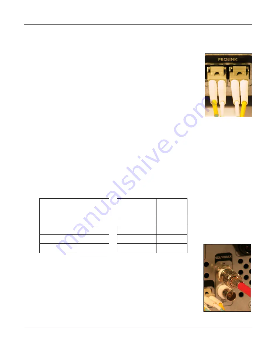
Connecting the VIP-4060 to the DVX LED display requires duplex LC fiber-optic
cables. To connect the VIP-4060 to the display, follow the steps below while
referring to
Figure 1
:
1.
Locate Port A and Port B on the back of the VIP-4060.
Note:
Both ports can be used to connect primary data and back-up data to
the display.
2.
Insert the duplex LC fiber-optic cables into their corresponding ports.
The cables will click into place when seated properly. Match the supplied
cable label to the port label.
Note:
Remove fiber dust covers from cables prior to inserting into ports.
Video System
There are four video feed options - DVI, 720p SDI, 1080p @30fps SDI, or Daktronics V-Max
™
signal - for
connecting a video feed to the VIP-4060 system. The type of video feed determines which will be used. In
stand-alone systems, the options are generally 720p SDI or DVI. Daktronics-supplied control systems use
V-Max
™
4 signal output to connect components.
Note:
DVI resolutions up to SXGA are supported (i.e. 640x480, 800x600, 1024x720, 1280x720, 1280x960,
1280x1024, 1400x900).
Supported DVI/VGA Resolutions
Video Standard
Resolution
(Pixels)
Video Standard
Resolution
(Pixels)
VGA
640x480
WXGA
1360x768
SVGA
800x600
SXGA
1280x960
XGA
1024x768
SXGA
1280x1024
WXGA
1280x720
WXGA+
1440x900
Connecting SDI or Daktronics V-Max
™
4 Signal
To connect the video feed to the VIP-4060 system, follow the steps below:
1.
Connect the BNC cable to the top SDI/V-Max
™
4 input. Refer to
Figure 2
.
2.
Rotate the connector a quarter turn clockwise to lock.
3.
Ensure that a 75 ohm terminator is connected to the bottom BNC.
Note:
The bottom BNC does not function as a loop out on the VIP-4060.
Figure 1:
Fiber-Optic Ports
Figure 2:
SDI/V-Max
™
4
Input


