


User Interface Basics 15
Section 3: User Interface Basics
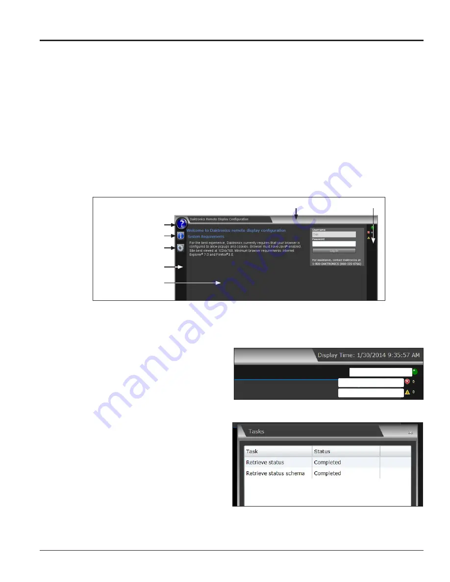
The VIP-4060 system’s application windows share common elements that are always visible to the user,
including a basic header bar, presentation area, right column, and left column. Refer to Figure 38.
3.1 Window Basics
• Header Bar
contains the application title
Daktronics Remote Display Configuration
.
• Presentation Area
displays elements, information, and data related to current user selections and
system triggers. Settings that can be modified by the user are shown in this area.
• Right Column
indicates the VIP-4060 communication status.
• Left Column
contains icons and tools. The basic
Help/Manual
,
About
, and
Communication settings
icons are always available. Following login, other icons and tools become available to the user.
Header Bar
Right Column
Help/Manual
About
Communication Settings
Left Column
Presentation Area
Figure 38:
Remote Display Configuration Screen
3.2 Communication Indicators
This section details the tools and features
available in the right column. Refer to
Figure 39
and
Figure 40
.
Communication Status
• Possible
or
Active
– A green light
indicates that communication is
possible between the application
and the VIP-4060. A blinking green
light indicates that communication is
actively taking place. Refer
to
Figure 39
.
Tasks
– Click the green communication
status indicator light to view the
Tasks
window. The open
Tasks
window lists
the tasks currently pending or recently
completed. Each task is listed as failed,
completed, or pending. Refer to
Figure 40
.
Note:
Do not drag the Tasks window outside the presentation area.
Communication status
Pending communication
Failed communication
Figure 39:
Right Column Communication Features
Figure 40:
Communication Tasks Window


