background image

DFX-7

 Ultrasonic Flaw Detector 

 TRIGGER 

CURVE 

PROBE FREQ 

LANGUAGE 

DELETE ONE 

FILE 

KEY CLICK 


 DPOLARITY 

CURV 

SIZE(ERS) 

 DELETE 

ALL 

DATA 

GAUGE  

 FIT 

ATTENUATION 


DELAY 

VELOCITY 


REF TYPE 


REF SIZE 


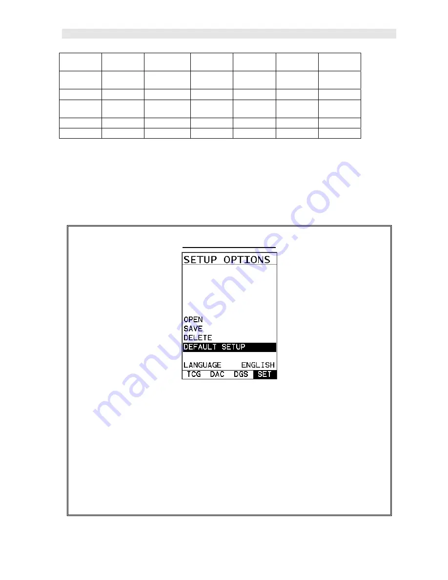
2.4 Loading the Default Setup 

 
If the 

DFX-7

 has previously been used, the basic default settings can be reloaded at 

any time, as outlined below: 
 

Load Default Setup 


The following section assumes the gauge is powered up, the flaw detector 

option selected, and the main measurement screen is being displayed. 

1)  Press the 

MENU

 key once to activate the menu items tab.  Press the 

MENU


key multiple times to tab right and the 

ESC

 key multiple times to tab left until 

the 

SET 

menu is highlighted and displaying the submenu items. 

2)  Use the 

UP

 and 

DOWN

 arrow keys to scroll through the sub menu items 

until 

DEFAULT SETUP

 is highlighted. 

Summary of Contents for DFX-7

Page 1: ...OPERATION MANUAL DAKOTA ULTRASONICS D DF FX X 7 7 Ultrasonic Flaw Detector Manual 2 of 2 P N P 220 0006 Rev 2 0 July 2017...

Page 2: ......

Page 3: ...US 7 3 2 PROBE MENU 9 3 3 CAL MENU 9 3 4 DISP DISPLAY MENU 10 3 5 TUNE MENU 10 3 6 GT1 MENU 11 3 7 GT2 MENU 12 3 8 TRIG MENU 12 3 9 AWS MENU 13 3 10 TCG MENU 13 3 11 DAC MENU 14 3 12 DGS MENU 14 3 13...

Page 4: ...BEAM CALIBRATION 47 CHAPTER SIX TRIGONOMETRY MODE 51 6 1 INTRODUCTION TO TRIG 51 6 2 ADDITIONAL COMMENTS 51 6 3 SETUP TRIGONOMETRY MODE 52 CHAPTER SEVEN AWS WELD INSPECTION 56 7 1 INTRODUCTION TO AWS...

Page 5: ...11 13 DETECT MARK 99 11 14 FILTERS WIDE NARROW BANDS 100 11 15 GAIN STEP SIZE 101 11 16 DETECT MODES 103 11 17 POLARITY 104 11 18 AUTO FIND 106 11 19 COMPARE 107 11 20 SET DATE TIME 108 11 21 SHOW DA...

Page 6: ...13 4 DELETING A SAVED SETUP 146 13 5 USING THE DEFAULT SETUP 148 13 6 SELECTING A LANGUAGE 150 CHAPTER FOURTEEN USING THE UTILITY SOFTWARE 151 14 1 COMPUTER SYSTEM REQUIREMENTS 151 14 2 INSTALLING DAK...

Page 7: ...ombines the two types of gauges into one powerful and full featured instrument that s equipped with a number of comprehensive toolkits to provide the user the arsenal necessary to address a number of...

Page 8: ...1 2 Electrical Warning The DFX 7 contains a high voltage pulser It s recommended that the gauge be powered off prior to connecting or disconnecting your transducer to avoid damaging the DFX 7...

Page 9: ...use the UP DOWN arrow keys to select flaw detector followed by pressing the OK key start the DFX 7 in flaw mode If this is the first time the gauge has been used a general startup configuration will...

Page 10: ...illustrated below Refer to Chapter Three for additional definitions and information on the keypad and menu items Start PRB CAL DISP TUNE GT1 GT2 TRIG AWS TYPE MAT VIEW FILTER ALARM 1 ALARM TRIG AWS PU...

Page 11: ...ny time as outlined below Load Default Setup The following section assumes the gauge is powered up the flaw detector option selected and the main measurement screen is being displayed 1 Press the MENU...

Page 12: ...Dakota Ultrasonics 6 3 Press the ENTER key to display the confirmation screen 4 Press the OK key to load the default setup and return to the measurement screen...

Page 13: ...enu tab groups These tab groups then contain sub menu items or functions The sub menu items have been organized in the tab groups according to how closely they are related to the individual tab group...

Page 14: ...familiar with activating and moving amongst the tab groups let s have a look at how to move around in the sub menu items as follows 2 Use the UP and DOWN arrow keys to scroll through the sub menu ite...

Page 15: ...00 ohms Refer to page 86 for further info PULSER VOLTAGE Adjustable pulser voltage 100 150 and 200 volt Refer to page 87 for a further explanation 3 3 CAL Menu MAT Select the material velocity from a...

Page 16: ...or further info LANDSCAPE Displays the A Scan waveform in landscape view for a larger viewable area with either right or left hand option Refer to page 95 for further info DIM Allows the user to conse...

Page 17: ...w the gates threshold level Refer to page 31 for further info GATE 1 Gates allow the user to view a specific inspection measurement range or specific regions of the waveform while ignoring others In o...

Page 18: ...ance from the GATE2 setting Refer to page 31 for further info THRESHOLD 2 Enables the user to set the sensitivity level of Gate2 to a calibrated screen height percentage The threshold level will act a...

Page 19: ...ation Rating IR Refer to page 56 for further info REFERENCE GAIN The gain in dB required to set the indication level to a specific percentage of full screen height FSH This value will typically be set...

Page 20: ...ggled at any time Refer to page 61 for further info TRIGGER CURVE Used to set the alarm threshold for the DAC curve The options are at DAC 2dB 6dB 10dB 12dB 14dB or using an independent gate The list...

Page 21: ...erences between the reference standards versus test material Refer to page 76 for further info DVK Used to correct for increases in gain based on a curved reference standard to an actual back wall ref...

Page 22: ...ith auto identifiers It is equipped with custom parameters rows and columns depending on the user s application reporting requirements Refer to page 117 for further info EDIT Gives the user the abilit...

Page 23: ...BOTH Refer to page 110 for further info KEY CLICK Gives the user the ability to set the level of the key press beeper OFF QUIET or LOUD Refer to page 107 for further info GAUGE Gives the user the abi...

Page 24: ...o row number option Finally when the TRIG feature has been activated pressing the OK multiple times will toggle through sound path surface distance or depth and displayed in the Hot Menu area 3 20 ESC...

Page 25: ...or OFF Note Unit will automatically power off when idle for 5 minutes All current settings are automatically saved prior to powering off 3 25 DFX 7 Overview In order to understand how to operate the...

Page 26: ...ch skip leg the detection in on The thickness of the material is used to calculate the leg F Hot Menu items We call this menu section our hot menu as these items are the most commonly adjusted feature...

Page 27: ...Menu s contain all the most regularly adjusted features of the gauge The primary purpose of the design was to provide the user with an efficient way to make adjustments on the fly during inspections...

Page 28: ...he gate and below will detect on anything that meets or is below the height of the gate 3 Alternatively press the ENTER key to display the Digits Edit Box 4 Press the UP and DOWN arrow keys to scroll...

Page 29: ...isk shown in the diagram Note This same disk is also used as a probe zero disk Simply remove the cover when replacing the batteries 3 AA cells When performing a manual probe zero function simply place...

Page 30: ...sitive or negative from the reflector or return echo The user can select the polarity or phase displayed This is typically determined by first using RF view to select the most optimal polarity phase t...

Page 31: ...pose we had a 50 widescreen television set The left side of the television screen is considered the Delay for all view options The right side of the television screen is the Range Delay By adjusting t...

Page 32: ...to scroll the highlighted value 3 Alternatively press the ENTER key to display the Digits Edit Box 4 Press the UP and DOWN arrow keys to scroll the highlighted value 5 Press the LEFT and RIGHT arrow k...

Page 33: ...iple times to move left until the RANGE cell is highlighted 2 Press the UP DOWN LEFT and RIGHT arrow keys to scroll the highlighted value 3 Alternatively press the ENTER key to display the Digits Edit...

Page 34: ...lack of detection on internal flaws pits or porosity The gain can easily be compared to the volume control of a home stereo system If you turn it up too much you can t hear the music clearly If it s...

Page 35: ...ow keys to scroll the highlighted value 5 Press the LEFT and RIGHT arrow keys to scroll the digit locations 6 Repeat steps 4 5 until the GAIN value is correctly displayed 7 Press the OK key to return...

Page 36: ...menu is highlighted and displaying the submenu items 2 Use the UP and DOWN arrow keys to scroll through the sub menu items until GAIN is highlighted 3 Press the LEFT and RIGHT arrow keys to scroll th...

Page 37: ...tion For example a test block with a target size and depth is optimized on the A Scan display with a signal amplitude at 70 full screen height The inspector wants to know of any defects during the ins...

Page 38: ...ab right and the ESC key multiple times to tab left until the GT1 menu is highlighted and displaying the submenu items 2 Use the UP and DOWN arrow keys to scroll through the sub menu items until ALARM...

Page 39: ...tions 5 Repeat steps 3 4 until the start position is correctly displayed 6 Press the OK key to set the GATE1 start position and return to the menu screen or ESC to cancel entering the GATE1 start posi...

Page 40: ...the UP and DOWN arrow keys to scroll the highlighted value 4 Press the LEFT and RIGHT arrow keys to scroll the digit locations 5 Repeat steps 3 4 until the threshold level is correctly displayed 6 Pre...

Page 41: ...DFX 7 Ultrasonic Flaw Detector 35 Note Sets where the detection will occur on the negative or positive going echoes...

Page 42: ...built into a single gauge a flaw detector and a thickness gauge Therefore while the flaw detector option can be calibrated for straight beam contact and angle beam style transducers the thickness gau...

Page 43: ...Loading Default Setup 1 Press the MENU key once to activate the menu items tab Press the MENU key multiple times to tab right and the ESC key multiple times to tab left until the SEUTP menu is highli...

Page 44: ...GT1 menu Note Our range calibration range for this example is 4 inches Therefore setting a range of 5 inches will enable the user to view the entire range on the display Enabling and Setting Up a Gat...

Page 45: ...highlighted 3 Press the LEFT and RIGHT arrow keys to toggle the gate ON Setting the Detect 1 Use the UP and DOWN arrow keys to scroll through the sub menu items until DETECT is highlighted 2 Press the...

Page 46: ...value is displayed Note In our example a value greater than 1 inch should be selected 6 Press the OK key to set the value and return to the GT1 menu Threshold Level 1 Use the UP and DOWN arrow keys to...

Page 47: ...ibration 5 2 Straight Beam Calibration Now that the DFX 7 is setup with a valid range and a gate enabled we re ready to perform a two point calibration using a single element contact style transducer...

Page 48: ...S key multiple times to move right and the ESC key multiple times to move left until the GATE1 cell is highlighted 2 Press the LEFT and RIGHT arrow keys to move the gate over the waveform to be measur...

Page 49: ...eat steps 4 5 until the known thickness value is correctly displayed 7 Press the OK key to calculate the velocity and return to the menu screen or ESC to cancel the one point calibration Apply a drop...

Page 50: ...te over the waveform to be measured as demonstrated in the screen shot above Note In order to trigger on a signal the waveform must be inside the boundaries of the gate Calibrating the Second Point 1...

Page 51: ...e one point calibration Note A velocity and zero value will be calculated and displayed in the fields a shown above 8 Finally press the MEAS key to return to the measurement screen In order to trigger...

Page 52: ...le times to move right and the ESC key multiple times to move left until the GATE1 cell is highlighted 2 Press the LEFT and RIGHT arrow keys to move the gate start to a position less than 1 inch 3 Pre...

Page 53: ...gle element straight beam contact transducer With the exception of a handful of additional comments calibration using an angle beam transducer is virtually identical in the scope of the overall step b...

Page 54: ...on the calibration standard The user should select a screen height and gain level that will enable the entire waveform to be visible on the display Peaking Up the Signal Amplitude During an angle beam...

Page 55: ...ighlighted and displaying the submenu items 2 Press the LEFT and RIGHT arrow keys to toggle TRIG mode ON 3 Press the MENU key once to activate the menu items tab Press the MENU key multiple times to t...

Page 56: ...rasonics 50 7 Press the ENTER key to select the material type and initiate the overwrite confirmation screen 8 Press the OK key to confirm the material selection or ESC key to cancel changing the mate...

Page 57: ...e weld at a given angle Therefore in order to determine the location of a defect given a specific angle the trigonometry mode is used This section will cover the steps to setup and utilize trigonometr...

Page 58: ...lat surface will using a transducer with a given angle The user should consider the angle used on curved surfaces with respect to the material thickness in order to be sure a reflection will occur fro...

Page 59: ...the sub menu items until TRIG is highlighted 3 Press the LEFT and RIGHT arrow keys to toggle the TRIG feature ON The menu items should now become active and adjustable as illustrated above Enter Mater...

Page 60: ...Edit Box 3 Press the UP and DOWN arrow keys to scroll the highlighted value 4 Press the LEFT and RIGHT arrow keys to scroll the digit locations 5 Repeat steps 3 4 until the angle is correctly display...

Page 61: ...vely press the ENTER key to display the Digits Edit Box 3 Press the UP and DOWN arrow keys to scroll the highlighted value 4 Press the LEFT and RIGHT arrow keys to scroll the digit locations 5 Repeat...

Page 62: ...Level IL C Attenuation Factor AF or 2 SP 1 SP sound path in inches 2dB loss per inch of material thickness D Indication Rating IR Note all values are in dB Calibration Standards Calibration In order t...

Page 63: ...nu is highlighted and displaying the submenu items 2 Use the UP and DOWN arrow keys to scroll through the sub menu items until AWS is highlighted 3 Press the LEFT and RIGHT arrow keys to toggle the AW...

Page 64: ...creen height Setting the Reference Gain 1 Press the UP and DOWN arrow keys until SET REF HEIGHT is highlighted followed by pressing the LEFT and RIGHT arrow keys to toggle the feature ON 2 Press the M...

Page 65: ...t until the AWS BOX cell is highlighted 2 Press the LEFT and RIGHT arrow keys to position the cursor box over the waveform 3 Press the ENTER key to set the REFGN reference gain Note This process can b...

Page 66: ...Dakota Ultrasonics 60 Note The AWS screen can be toggle on by pressing the OK key while in the main measurement screen Equally the Hot Menus can be toggled by pressing the MEAS at any time...

Page 67: ...set to TRIGGER on any of the curve options displayed Therefore if the 6 12dB curve option has been selected the user can toggle the TRIGGER options GATE DAC 6dB or 12dB Note Based on the screen resol...

Page 68: ...ver a waveform to use as a point in generating the DAC curve the DAC BOX hot menu item in the main measurement screen must be highlighted 8 3 Creating a DAC Curve This section provides a step by step...

Page 69: ...ow keys to toggle and select dB FSH or DAC Selecting the Curve s 1 Press the UP and DOWN arrow keys until CURVE is highlighted followed by pressing the LEFT and RIGHT arrow keys to toggle and select D...

Page 70: ...eys to select SPLINE or LINEAR 2 Proceed to the next section Drawing the DAC Drawing the DAC 1 With all the parameters set in the previous section press the MEAS key once to return to the main measure...

Page 71: ...t within the boundaries of the waveform display area and at a suitable height to allow for attenuation at greater depths in the overall range to be tested 4 Press the LEFT and RIGHT arrow keys to move...

Page 72: ...ab right and the ESC key multiple times to tab left until the DAC menu is highlighted and displaying the submenu items 7 Press the UP and DOWN arrow keys until DRAW is highlighted followed by pressing...

Page 73: ...better solution for any materials that attenuate more than 18dB over the inspection range and should be considered 9 2 Additional Comments Prior to proceeding onto the next section to create a DAC cur...

Page 74: ...toggle the TCG feature ON The menu items should now become active and adjustable as illustrated above Enter Screen Height 7 Press the UP and DOWN arrow keys until SCRN HEIGHT is highlighted followed b...

Page 75: ...ub menu items until DRAW is highlighted 5 Press the LEFT and RIGHT arrow keys to toggle the DRAW feature ON 6 Proceed to the next section Drawing the TCG curve Drawing the TCG 1 With all the parameter...

Page 76: ...s the LEFT and RIGHT arrow keys to move the cursor over the waveform to be used as the first point in the TCG curve and press the ENTER key to set the first point Illustrated in ex 1 above 5 Repeat st...

Page 77: ...IGHT arrow keys until OFF is displayed The TCG curve is now set 8 Optionally the TCG curve can be displayed by pressing the UP and DOWN arrow keys until CURVE is highlighted followed by pressing the L...

Page 78: ...ethods DGS can be thought of as a mathematically derived DAC curve and used as an alternative replacement for DAC The concept of the DGS method is to compare the amplitude gain of similar reflectors a...

Page 79: ...2 6dB However a defect reflector that s less than or equal to the effective diameter of the transducer doubling the distance decreases the sound energy by 1 4 12dB at D The curve at E represents a de...

Page 80: ...diameter the shape of the crystal must be taken into account Transducers are either round or square rectangular in shape and can be approximated as follows Round Crystal DEFF Where DEFF Effective Dia...

Page 81: ...ated results can also be compared to the following table Ratio of the sides B A K 1 0 1 37 0 9 1 25 0 8 1 15 0 7 1 09 0 6 1 04 0 5 1 01 0 4 1 00 0 3 0 99 0 2 0 99 0 1 0 99 10 4 Parameter Definitions D...

Page 82: ...etween the two closest curves and mathematically derive a curve for that value Attenuation Used to additionally compensate other factors leading to the loss of sound energy Refer to section 10 5 for m...

Page 83: ...for the attenuation loss of sound energy in the calibration reference standard in units of dB in or dB meter Transfer Loss Correction factor to account for the loss of sound energy from surface condi...

Page 84: ...eys to toggle the DGS feature ON The menu items should now become active and adjustable as illustrated above Trigger Curve 1 Press the UP and DOWN arrow keys multiple times until TRIGGER CURVE is high...

Page 85: ...quency 1 Press the UP and DOWN arrow keys multiple times until PROBE FREQUENCY is highlighted followed by pressing the LEFT and RIGHT arrow keys to scroll the value When the correct frequency is displ...

Page 86: ...ERS and return to the menu screen or ESC to cancel entering the ERS Attenuation All Parameters 1 Press the UP and DOWN arrow keys multiple times until ATTENUATION is highlighted followed by pressing...

Page 87: ...alue Drawing the DGS Curve 1 Press the UP and DOWN arrow keys multiple times until REFERENCE GAIN is highlighted followed by pressing the LEFT and RIGHT arrow keys to toggle on With all the parameters...

Page 88: ...ed 3 Press the LEFT and RIGHT arrow keys to move the cursor over the waveform that will be used to set the REFERENCE GAIN and draw the DGS curve Note The DGS curve uses 16 points to plot the curve 4 P...

Page 89: ...etector 83 5 Press the UP and DOWN arrow keys multiple times until REFERENCE GAIN is highlighted followed by pressing the LEFT and RIGHT arrow keys to toggle OFF The DGS curve is now set and ready to...

Page 90: ...rgy is needed more penetration the THIN and WIDE options may be necessary The standard setting is THIN The procedure to change the pulse width is outlined below Selecting the Pulse Width 1 Press the M...

Page 91: ...as a response rate of less than 60Hz The PRF setting will automatically be overridden according to the range set by the user Long range settings will slow the PRF down automatically Slower PRF setting...

Page 92: ...her impedance and distort The reverse is true for higher frequency transducers Nevertheless trial and error with this feature will enable you to find the optimal signal response and setting for your t...

Page 93: ...ial types or increased resolution on noisy materials The procedure to change the pulser voltage is outlined below Changing the Pulser Voltage 1 Press the MENU key once to activate the menu items tab P...

Page 94: ...e must be activated as we ve assumed an angle beam transducer will be used for the inspection process The procedure is listed below Selecting a Basic Material Type 1 Press the MENU key once to activat...

Page 95: ...selected 6 Finally press the MEAS key to return to the measurement screen and begin taking readings 11 6 Material Velocity The DFX 7 has a built in feature to manually adjust the material velocity to...

Page 96: ...ed proceed to step 8 4 Alternatively press the ENTER key to display the Digits Edit Box 5 Press the UP and DOWN arrow keys to scroll the highlighted value 6 Press the LEFT and RIGHT arrow keys to scro...

Page 97: ...ghted and displaying the submenu items 2 Use the UP and DOWN arrow keys to scroll through the sub menu items until ZERO is highlighted 3 Press the LEFT and RIGHT arrow keys to scroll the value When th...

Page 98: ...0 representing the brightest setting The procedures for adjusting the brightness are outlined below Adjusting Brightness 1 Press the MENU key once to activate the menu items tab Press the MENU key mul...

Page 99: ...s number is correctly displayed 8 Press the OK key to set the brightness and return to the menu screen or ESC to cancel entering the brightness 9 Finally press the MEAS key to return to the measuremen...

Page 100: ...g the submenu items 2 Use the UP and DOWN arrow keys to scroll through the sub menu items until VIEW is highlighted 3 Press the ENTER key to display a list of the color scheme options 4 Press the UP a...

Page 101: ...on will be expanded to include the entire 2 7 AMOLED display improving the overall visibility during inspections The procedures for enabling LANDSCAPE and toggling between portrait and landscape views...

Page 102: ...s will toggle through all of the measurement available for display 11 11 DIM The DFX 7 has a built in DIM feature to manage power more effectively This feature has adjustable time durations until the...

Page 103: ...LEFT and RIGHT arrow keys to scroll the DIM time 4 Finally press the MEAS key to return to the measurement screen and begin taking readings 11 12 Graphics Options look feel The DFX 7 includes a couple...

Page 104: ...Dakota Ultrasonics 98 Filled Draws a filled version of the waveform The procedure to select the look and feel option is outlined below Setting the Look Feel...

Page 105: ...LEFT and RIGHT arrow keys to scroll the RECT WAVE options 4 Once the RECT WAVE is displayed press the MEAS key to return to the measurement screen 11 13 Detect Mark Another look and feel option of the...

Page 106: ...Hz The DFX 7 includes the same wide band filter but also includes a few narrow band filter options at 2MHz 5MHz and 10MHz The wide band option is responsive to all signals within the given frequency r...

Page 107: ...eft until the TUNE menu is highlighted and displaying the submenu items 2 Use the UP and DOWN arrow keys to scroll through the sub menu items until FILTERS is highlighted 3 Use the LEFT and RIGHT arro...

Page 108: ...GAIN STEP is highlighted 3 Press the LEFT and RIGHT arrow keys multiple times using the left button wheel to scroll the value When the correct step size is being displayed proceed to step 8 4 Alternat...

Page 109: ...Cross Flank Peak Refer to the diagrams above The current polarity is positive as shown by the position of the gate above the baseline Z Cross The detection occurs as the first positive half cycle cros...

Page 110: ...of a gate If a polarity view of RECT is selected only the positive portion of the waveform will be shown on the screen If a positive polarity is then selected for GT1 not only will the gate be displa...

Page 111: ...ver if it was set to negative would not appear on the display In the example above the gate is set to positive and will detect on the positive going waveform cycles shown in the box B Toggle Polarity...

Page 112: ...s the MEAS key to return to the measurement screen and begin taking readings 11 18 Auto Find The DFX 7 is equipped with a very handy feature for locating the detection point of a return echo that is n...

Page 113: ...UTO FIND is highlighted 3 Place the transducer on the test material and obtain a reading 4 Press the ENTER key to automatically adjust the display settings and bring the waveform into view 5 Once the...

Page 114: ...law on the display and press the MULTI MODE key to display the submenu items 6 Use the UP and DOWN arrow keys to scroll through the submenu items until PEAK is highlighted 7 Press the ENTER key to fre...

Page 115: ...highlighted and displaying the submenu items 2 Use the UP and DOWN arrow keys to scroll through the sub menu items until SET DATE is highlighted 3 Press the ENTER key to display the Digits Edit Box 4...

Page 116: ...preferred off date time both The procedure for activating and displaying the above options are outlined below Live Time Date 1 Press the MENU key once to activate the menu items tab Press the MENU ke...

Page 117: ...to tab left until the UTIL menu is highlighted and displaying the submenu items 2 Use the UP and DOWN arrow keys to scroll through the sub menu items until KEY CLICK is highlighted 3 Use the LEFT and...

Page 118: ...needed It should also be mentioned that this feature is immediately activated on boot up Therefore all the menus items list boxes and edit screens can also be captured for presentation or training pu...

Page 119: ...urement screen 11 24 Peak Hold The DFX 7 includes a peak hold feature that draws and saves the maximum waveform amplitude on the screen This allows an inspector to move the transducer in all direction...

Page 120: ...Disabling PEAK Note In order to deactivate the PEAK hold feature 1 Press the MULTI MODE key located in the bottom left corner of the keypad to display the mode options 2 Use the UP and DOWN arrow keys...

Page 121: ...P and DOWN arrow keys FREEZE is highlighted 3 Press the ENTER key to set the mode and automatically return to the measurement screen Disabling Freeze Note In order to deactivate the FREEZE feature 3 P...

Page 122: ...wable characters that will be used for both file formats GRID SEQ LOG Any combination of these characters can be used for creating a Name and Note regardless of the selected format The allowable chara...

Page 123: ...all references to GRIDS and SEQ LOGS should be considered synonymous with references to FILES 12 2 Creating a new Grid or Sequential Log File Important Note This entire section is a step by step guide...

Page 124: ...l Log 1 Press the MENU key once to activate the menu items tab Press the MENU key multiple times to tab right and the ESC key multiple times to tab left until the DATA menu is highlighted and displayi...

Page 125: ...and DOWN arrow keys to scroll through the new Grid or Seq List Items until NAME is highlighted 6 Press the ENTER key to activate the Alpha Edit Box 7 Use the UP DOWN LEFT RIGHT arrow keys to highligh...

Page 126: ...to cancel entering the Grid or Seq Name File Name Creating a Note Grid Seq Log Note Can contain a combination of up to 20 numeric alpha or special characters listed in the first section of this chapt...

Page 127: ...List Items menu or ESC to cancel entering the Grid or Seq Note Setting the Coordinates or Start Stop ID s Grid A grid is defined by using coordinates to define the Top Left and the Bottom Right corne...

Page 128: ...can consist of a combination of up to 20 of the same character set Note The identifier cannot start or end with a special character Once a start and end ID are entered into the DFX 7 and the log creat...

Page 129: ...o highlight the appropriate alpha characters Press the ENTER key to select a character and advance to the next character field in conjunction with using the CLR key to backspace if necessary 4 Press t...

Page 130: ...ID is highlighted 2 Press the ENTER key to activate the Coordinate or End ID Edit Box Grid Log Sequential Log 3 GRID LOG Use the LEFT RIGHT arrow keys to scroll the Columns and the UP DOWN arrow keys...

Page 131: ...st Items screen or ESC to cancel the selection and return to the Grid or Seq List Items menu Note If there is not enough memory available to create the grid or sequential log an error message box NOT...

Page 132: ...ing Grid Log Sequential Log 5 Use the UP and DOWN arrow keys to scroll through the new Grid or Seq List Items until INCR DIR or DIRECTION is highlighted 6 Use the LEFT RIGHT arrow keys to toggle the I...

Page 133: ...reas for reporting purposes It might also come in handy when user requires backup of all the current DFX 7 parameters for each reading However if neither of these requirements are necessary this optio...

Page 134: ...ption of saving or canceling the new grid Grid Log Sequential Log 4 Use the UP and DOWN arrow keys to scroll through the new Grid or Seq List Items until CREATE GRID or LOG is highlighted 5 Press the...

Page 135: ...owing the create confirmation screen It is located at the bottom of the measurement screen and can be left open for the duration of the inspection process This section assumes the grid or sequential l...

Page 136: ...the GRID SEQ View Box or ENTER to display it as necessary Note Once the file is open it will remain open until it s closed or another file is opened by the user If the gauge is powered off the DFX 7 w...

Page 137: ...EFT and RIGHT arrow keys to scroll the stored readings and corresponding display view Notice as the cursor is moved to a different cell the display will be updated with the display view saved with the...

Page 138: ...m Memory Deleting One File 1 Press the MENU key once to activate the menu items tab Press the MENU key multiple times to tab right and the ESC key multiple times to tab left until the DATA menu is hig...

Page 139: ...target File to delete is highlighted 5 Press the OK key to delete the File 6 Press the MEAS key to return to the measurement screen Deleting All Data 1 Press the MENU key once to activate the menu ite...

Page 140: ...croll through the sub menu items until DELETE ALL DATA is highlighted 3 Press the ENTER key to activate the confirmation screen 4 Press the OK key to delete All Files from memory or the ESC key to abo...

Page 141: ...tab right and the ESC key multiple times to tab left until the DATA menu is highlighted and displaying the submenu items 2 Use the UP and DOWN arrow keys to scroll through the sub menu items until EDI...

Page 142: ...editing the NOTE 6 Use the UP DOWN LEFT RIGHT arrow keys to highlight the appropriate alpha characters 7 Press the ENTER key to select a character and advance to the next field of the Comments 8 Use...

Page 143: ...screen 12 7 Changing the active File Open The user may have transferred grid seq templates from a PC to the DFX 7 or setup grids seq using the DFX 7 at an earlier time The name of the currently active...

Page 144: ...the ESC key multiple times to tab left until the DATA menu is highlighted and displaying the submenu items 2 Use the UP and DOWN arrow keys to scroll through the sub menu items until OPEN is highlight...

Page 145: ...ser might not have a current requirement to store measurements but a file is currently open or active and needs to be closed The following procedures outline how to close an open or active file Closin...

Page 146: ...arrow keys to scroll through the sub menu items until CLOSE is highlighted 3 Press the ENTER key to close the active file Note Following the key press the CLOSE text will be grayed out indicating the...

Page 147: ...ups These setups can be bi directionally transferred to and from a PC Therefore the user can save as many setups as necessary for all their individual applications requirements This saves a great deal...

Page 148: ...ESC key multiple times to tab left until the SETUP menu is highlighted and displaying the submenu items 2 Use the UP and DOWN arrow keys to scroll through the sub menu items until OPEN is highlighted...

Page 149: ...a specific setup location for future use This can potentially save time and reduce error between users It is sometimes necessary to rename a previously saved setup or add additional comments about a p...

Page 150: ...the ESC key multiple times to tab left until the SETUP menu is highlighted and displaying the submenu items 2 Use the UP and DOWN arrow keys to scroll through the sub menu items until SAVE is highligh...

Page 151: ...he characters the ENTER key to select characters and the CLR key to backspace through the characters until the Name or Note fields have been edited 7 Press the OK key to return to the Save Setup Param...

Page 152: ...Setup 14 Finally press the MEAS key to return to the measurement screen Note The Name and Comments of the Setup can be edited at any time by simply repeating the Save Setup routine described above Th...

Page 153: ...mes to tab right and the ESC key multiple times to tab left until the SETUP menu is highlighted and displaying the submenu items 2 Use the UP and DOWN arrow keys to scroll through the sub menu items u...

Page 154: ...d in the gauge factory or otherwise The only time this might possibly occur is if the setup file in the DFX 7 was somehow corrupted and the user does not have access to a computer to re load the facto...

Page 155: ...tivate the menu items tab Press the MENU key multiple times to tab right and the ESC key multiple times to tab left until the SETUP menu is highlighted and displaying the submenu items 2 Use the UP an...

Page 156: ...NU key once to activate the menu items tab Press the MENU key multiple times to tab right and the ESC key multiple times to tab left until the SETUP menu is highlighted and displaying the submenu item...

Page 157: ...r with at least 32 megabytes of physical RAM is required You should have 40 megabytes of free disk space before attempting to install DakView File transfer is standard USB connectivity using a USB C t...

Page 158: ...DFX 7 The DFX 7 can be upgraded to the latest revision of firmware at any time Simply download the latest version posted on the Dakota Ultrasonics website copy the upgrade file to the main drive dire...

Page 159: ...Detector 153 2 Press the ENTER key to display the upgrade confirmation screen followed by pressing OK key to start the upgrade process Note The DFX 7 will power down during the upgrade process and re...

Page 160: ...ld 0 1280 3251 0470 1194 Inconel 0 2290 5817 1190 3020 Iron 0 2320 5893 1270 3230 Cast Iron 0 1800 4572 0870 1260 2200 3220 Lead 0 0850 2159 0280 700 Magnesium 0 2300 5842 1200 3050 Mercury 0 0570 144...

Page 161: ...ss 0 2230 5664 1230 3120 Teflon 0 0540 1372 2500 6350 Tin 0 1310 3327 0660 1670 Titanium 0 2400 6096 1230 3120 Tungsten 0 2040 5182 1130 2870 Uranium 0 1330 3378 0780 1980 Water 0 0580 1473 Zinc 0 166...

Page 162: ...156 APPENDIX B SETUP LIBRARY Num Name Comment 1 Gn AGC Velocity 1 Enter Custom Name 2 3 4 5 6...

Page 163: ...th respect to this product Dakota Ultrasonics specifically disclaims any implied warranties of merchantability or fitness for a particular purpose Some states or provinces do not allow limitations on...

Reviews: