[9]
MAN #650793
Special Operating Modes:
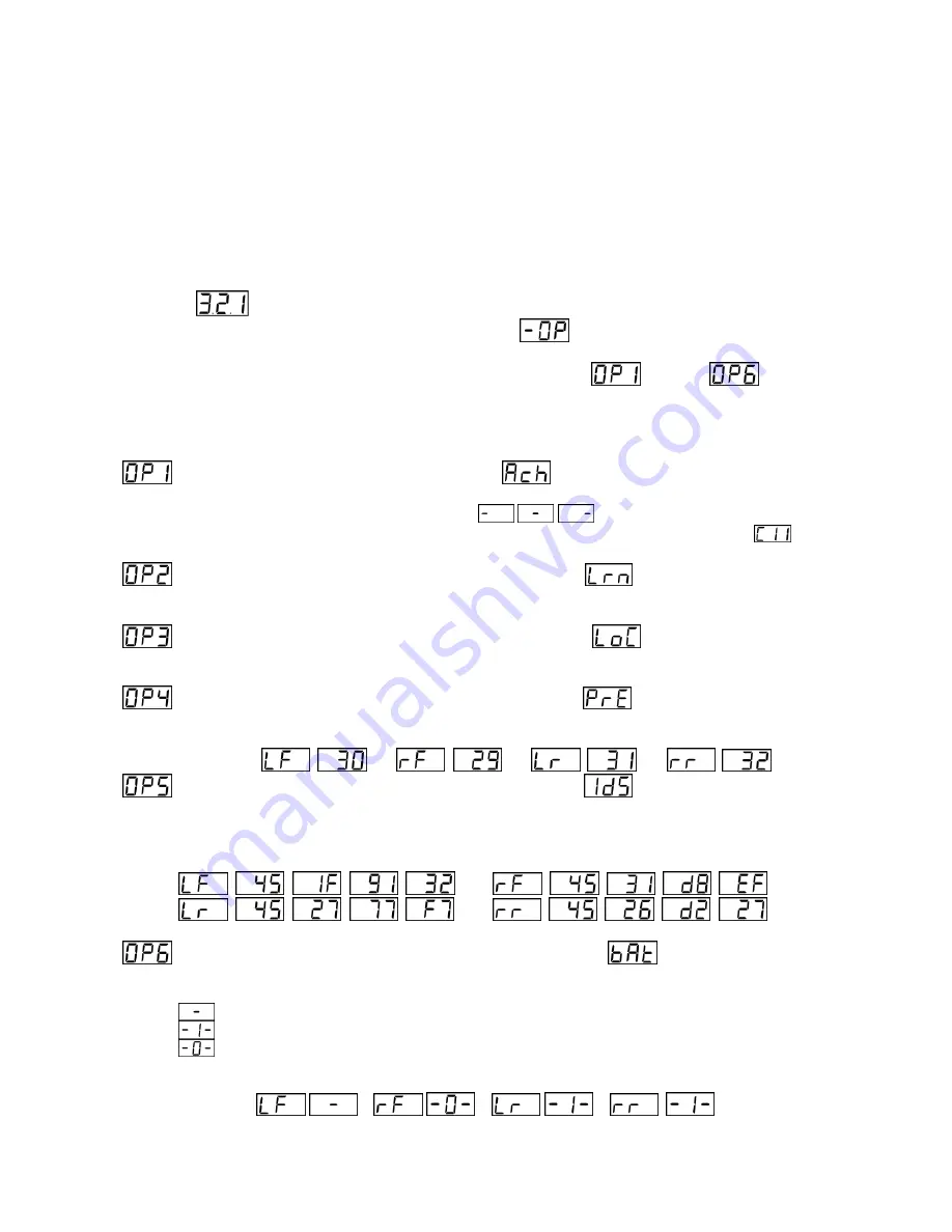
The BIM-22-3 has special operating modes that can be used for configuration or for reporting information on its display
for trouble-shooting purposes. Note:
Display Pressures Mode
and Display
Battery Status Mode
will not function
correctly until the sensors are in service mode. See
Understanding the Different Sensor Modes - Page 2
for
information on how to get the sensors into service mode.
These modes can be selected using the following steps:
Hold the switch on the BIM while turning the key on. The BIM display will show the current revision code while
the switch is being held.
Example:
Release the switch. The display will show the characters
to indicate you have entered the Special
Operating Modes menu.
Press and release the switch to cycle through the available modes.
through
are displayed as
you repeatedly press and release the switch.
The
Special Operating Modes
are as follows:
Auto ID Setup
. To select, press and hold until
is displayed.
This mode auto selects BIM channels for each sensor. Upon releasing the switch, the BIM display will
begin sequencing a bar across the display
while it auto detects channel IDs. After it
is complete, the BIM will display the ID of the first auto-selected channel (example:
). Turn the
key off then back on to have the system start up with this configuration.
BIM Learn Sensors Mode
. To select, press and hold until
is displayed.
This mode is used for learning new TPMS sensors in the event one or more is damaged. For more
information concerning this mode, refer to the section
BIM Learn Sensors Mode
– Page 11
.
BIM Locate Sensors Mode
. To select, press and hold until
is displayed.
This mode is used for locating sensors before installing the instrument system. For more information
concerning this mode, refer to the section
BIM Locate Sensors Mode
– Page 12
.
Display Pressures Mode
. To select, press and hold until
is displayed.
This mode continuously displays
each sensor’s location followed by its pressure. This will continue
until the next key off/on cycle.
Example:
Display Sensor IDs Mode
: To select, press and hold until
is displayed.
This mode continuously d
isplays each sensor’s location followed by its sensor ID. This is an 8 digit
alphanumeric number corresponding to the num
ber located next to the label “ASIC” on the sensor
itself. It is used by the TPMS Receiver Module to identify sensors. This display will continue until the
next key off/on cycle. See the example below:
Display Battery Status Mode
: To select, press and hold until
is displayed.
This mode continuously d
isplays each sensor’s location followed by its battery status. This will
continue until the next key off/on cycle.
- Is displayed if the sensor is inactive or missing.
- I
s displayed if the sensor’s battery is OK.
- I
s displayed if the sensor’s battery is low.
Under normal driving conditions, a low battery means you have approximately 2 months of
battery life left.
Example:
Summary of Contents for BIM-22-3
Page 15: ...15 MAN 650793 NOTES...


