[2]
MAN #650793
Introduction
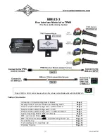
This Bus Interface Module (BIM) communicates with a TPMS Receiver Module which receives tire pressures and other
information from four TPMS sensors installed in a
vehicle’s tires.
There are three interface (I/O) ports on the module. Two of these can be connected to a Dakota Digital instrument
system or to another BIM, allowing several units to be daisy chained together. Do not connect these I/O ports to
anything other than a Dakota Digital control box or BIM. Ensure all BIM units are connected properly. On appropriate
VHX, VFD3, and VFD3X systems, use the BIM-XX-1 harness (not shown). On HDX, RTX, and other VHX, VFD3, and
VFD3X systems, use the BIM-XX-2 harness.
The interface labeled “INPUT” on the BIM-22-3 is connected to the TPMS Receiver Module using the TPMS Receiver
Module adapter harness.
The TPMS sensors transmit pressures and other information wirelessly through an RF signal. They are to be mounted
inside the vehicle’s tires; replacing normal valve stems. We recommend that the tires be rebalanced after TPMS
sensors are installed.
Do not mount the BIM-22-3, nor the TPMS Receiver Module, in the engine compartment
; they should be mounted
in the interior of the vehicle.
The BIM-22-3 should be installed in a location where its display and switch are accessible in the event a new TPMS
sensor needs to be installed in the system (see
BIM Learn Sensors Mode
). In situations where TPMS reception is not
adequate inside the interior of the vehicle, the weatherproof TPMS Receiver Module can be mounted outside on the
chassis near the center of the vehicle for better reception of the RF transmission signals from the TPMS sensors.
The BIM-22-3 system provides tire pressures in PSI (pounds per square inch) for each of the
vehicle’s four tires to a
control box. When the vehicle is first turned on, dashes will be displayed on the gauge until the sensors have activated
or “woken up” from their sleeping state. The sensors wake up by driving the vehicle or if a pressure change of at least
2 PSI has taken place. This behavior of going to sleep when the vehicle is not moving vastly prolongs a
sensor’s
battery life. After the sensors wake up, they report pressures to the TPMS Receiver Module, which in turn are reported
through the BIM-22-3 to the control box.
Understanding the Different Sensor Modes
OFF/SHIPPING
When sensors are shipped, they are in OFF/SHIPPING mode. In this mode the sensors will not take pressure
readings or transmit any information. This prolongs the shelf life of the battery in the sensor.
STATIONARY
When the sensors are installed into a tire and have pressure applied, the sensors will enter STATIONARY mode.
In stationary mode the sensor will take pressure readings every 60 seconds. By taking pressure readings every 60
seconds the sensor can determine when it sees a change in pressure. When a sensor sees a change in pressure of
greater than 2 PSI it will transmit its
“Learn” information to the receiver.
ROLL
Once a sensor is installed, under pressure and the vehicle is in motion the sensor will go into ROLL mode.
To ensure the sensors wake up and go into ROLL mode, the vehicle should be driven for at least 60 seconds at over
12.5 MPH (20 KPH).
In ROLL mode the sensors will regularly transmit data to the receiver once every 5 seconds.
SERVICE
After the sensors have been in ROLL mode and then the vehicle comes to a stop the sensors will enter SERVICE
mode and remain in this mode for 15 minutes.
In SERVICE mode the sensors will continue to sample and transmit pressure data every 5 seconds.
After the 15 minutes are up, the sensors revert back to STATIONARY mode.
The time required to do a sensor LEARN or LOCATE process can be greatly reduced, when the sensors are in
SERVICE mode.
Summary of Contents for BIM-22-3
Page 15: ...15 MAN 650793 NOTES...


