


PIM-00004
△
1
[Operation Manual]
20/61
DAIKIN INDUSTRIES, LTD.
Wiring procedure
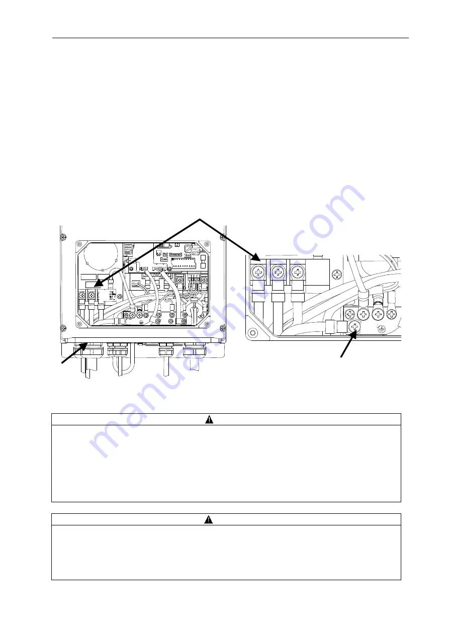
To connect the main power supply and I/O signal cables, remove the small cover of the controller.
Remove the controller small cover by loosening the cross recessed head machine screws (four M4 screws,
Tightening torque: 1.0 N
m).
Connecting the main power supply cable
(1) Connect the main power supply cable to the controller through the controller's wiring hole. Use a cable
clamp suitable for the wiring hole, whose protection rating should be IP54 or higher level. (Wiring hole
diameter: 28 mm)
[1] Connect the ground cable to the controller's ground terminal.
[2] Connect the power supply cable to individual terminals on the power supply terminal block.
(Tightening torque: 2.4 N
m)
Power supply terminal block
<When the unit controller small cover is removed>
<Enlarged view of power supply terminal block>
DANGER
Use an AC power supply conforming to the power supply specifications of this product.
Use a power supply cable conforming to the power supply capacity. (See the table below.)
Do not connect the power supply cable to the ground terminal.
The ground terminal is connected with the motor frame. Ensure Class D (former Class 3) or higher
grounding condition.
When unsheathing the cable, be careful not to damage the conductors.
Be careful that the cable conductors do not protrude from the terminal block.
CAUTION
For connection of the power supply cable, attach a crimp terminal to the tip of the cable.
The cable inserted into the cable clamp should be a multi-core cable as those recommended below.
If two or more cables are inserted into the clamp, the cable clamp does not conform to the specified
protection rating because of a gap between the cables and the cable clamp.
When connecting the cable, be careful not to drop a screw into the housing.
Wiring hole
Ground terminal
Connect a
ground cable to
the specified
position.
Ground
Connect a
ground
cable to the
specified
position.
Ground


