


11
English
(Refer to figure 26)
1.
R410A Tank (Siphon system)
2.
Measuring instrument
3.
Valve A
4.
Indoor unit
5.
Stop valve service port
6.
Gas line stop valve
7.
Outdoor unit
8.
Liquid line stop valve
State of valve A and the stop valve
Valve A
Liquid
line stop
valve
Gas line
stop
valve
Before starting to charge the refrigerant
Close
Close
Close
During charging of the refrigerant
Open
Close
Close
3. Close valve A after charging is complete.
Note: If all the refrigerant to be added cannot be charged using the
above procedure, re-charge the refrigerant as below.
If all the refrigerant could not be added
Add refrigerant referring to the “Service Precautions” plate attached to
the outdoor unit for details on the settings for adding refrigerant.
9. POST-WORK CHECKS
Perform the following checks after work is complete.
(1) Drain pipe connection, removal of transport bracket
→
See “
5. PRECAUTIONS ON INSTALLATION
”.
(2) Incorrect power supply wiring, loose screws
→
See “
7-3 How to connect the power supply wiring
”.
(3) Incorrect transmission wiring, loose screws
→
See “
7-4 Transmission wiring connection procedure
”.
(4) Incorrect refrigerant piping connections
→
See “
6. REFRIGERANT PIPING
”.
(5) Piping sizes, use of insulation
→
See : “
6-2 Selecting piping material
”.
“
6-6 Thermal insulation of piping
”.
(6) Stop valve check
→
Make sure both the liquid-side and gas-side stop valves are open.
(7) Record of Amount of Refrigerant Added
→
Record it on “Record of Amount of Refrigerant Added” on the “Ser-
vice Precautions” label.
(8) Measuring the insulation of the main power circuit
→
• Use a 500V mega-tester.
• Do not use the mega-tester for low voltage other than 208/230V.
(Transmission wiring)
CAUTION
To the piping installer
After completing installation, be sure to open the valves.
(Operating the unit with the valve shut will break the compressor.)
10. TEST OPERATION
This unit is equipped with a crank case heater to ensure smooth
startup. Be sure to turn the power on at least 6 hours before opera
-
tion in order to have power running to the crank case heater.
WARNING
When leaving the unit with the power on, be sure to switch
with another person doing the installation or close the front
panel.
Precautions before turning the power on
• Using insulating sheets, tape electric parts as described in the “Ser-
vice Precautions” label on the back of the front panel.
• The indoor unit connected to the outdoor unit operates automatically.
Complete work on the indoor unit in order to ensure maximum safety.
10-1
Power On–Check Operation
• Make sure to perform the check operation after installation.
(If the air conditioner is operated using the indoor remote controller
without performing the check operation, the malfunction code “U3” is
displayed in the indoor remote controller, and normal operation is
disabled.)
• When making settings on the outdoor unit PC board (A1P or A2P)
after turning the power on, do not touch anything other than the
push-button switches and dip switches.
(See the “Service Precautions” label for the locations of the push-
button switches (BS1-5) and dip switches (DS1-1, 2) on the PC
board (A1P or A2P).)
• During the operation, monitor the outdoor unit operation status and
check for any incorrect wiring.
1. Close the outdoor unit’s front panel.
Turn the power
on for the outdoor
unit and the indoor unit.
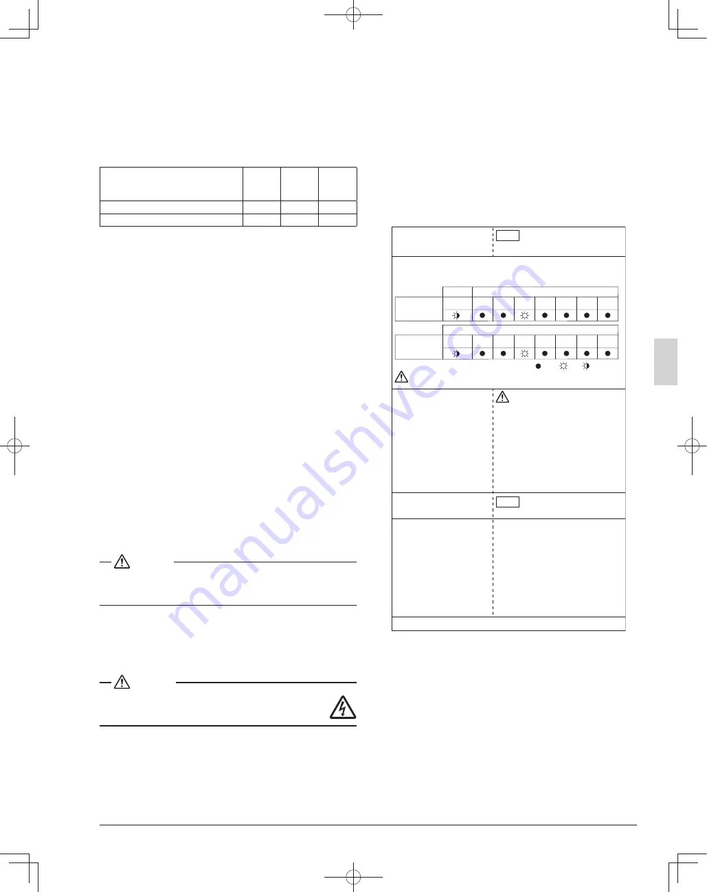
2. • Open the outdoor unit’s front panel.
• Make sure the LED display on the outdoor unit’s PC board (A1P or A2P) is
as shown in the following table.
6. Close the front panel of the outdoor unit after check operation is complete.
Do not leave any stop valve closed
otherwise the compressor will fail.
Caution
Be sure to turn the power on at least
6 hours before operation in order to have
power running to the crank case heater.
To avoid the risk of electric shock, do not touch anything other than the
push-button switches on the PC board (A1P or A2P) when making settings.
Caution
LED display
(Default status
before delivery)
HAP
<30~48 type>
A1P
H1P
H2P
H3P
H4P
H5P
H6P
H7P
LED display
(Default status
before delivery)
HAP
<18·24 type>
A2P
A1P
H1P
H2P
H3P
H4P
H5P
H6P
H7P
LED display: OFF ON Blinking
Use caution to avoid electric shock while
working, since the outdoor unit is on.
• Only set the push-button switches (BS1-5)
after making sure the operation pilot lamp on
PC board is lit up.
• See the “Service Precautions” label on the
back side of the front panel for details on how
to make the settings.
(Do not forget to write the settings down on
the “Service Precautions” label.)
• The dip switch (DS1-1) does not need to be
set, so do not touch it.
Doing so may cause malfunction.
• If you have to leave the outdoor unit during
check operation, either switch with another
worker or close the front panel.
• The system operates for about 30 minutes
(60 minutes at maximum) and automatically
stops the check operation.
• The system can start normal operation about
3 minutes
after the check operation if
the
remote controller does not display any
malfunction code.
The remote controller will show the test
operation display during check operation.
3. • When the customer requests
quiet operation or demand
operation, make these settings
using the push-button switches
(BS1-5) on the outdoor unit’s
PC board (A1P or A2P).
• Operate the push-button
switches through the opening
after protecting it with an
insulation cover.
(See the “Service Precautions”
label for details.)
4. • Check that the liquid and gas-side
stop valves are open, and if
they are closed, open them.
5. Press the test operation button
(BS4) for at least five seconds and
perform check operation.
For details, see “How to perform
check operation” on the “Service
Precautions” label.
<Precautions During Check Operation>
•
If operation is performed within 12 minutes of the indoor and
outdoor units being turned on, H2P will light up, and the com
-
pressor will not run.
Only perform operation after checking that the LED display is as
shown in “
10-1 Power On–Check Operation
” 2. table.
• In order to ensure uniform refrigerant distribution, it may take up to
around 10 minutes for the compressor to start up after the unit
begins running. This is not a malfunction.
• The check operation cannot be performed in other modes.
• If the discharge pipe thermistor (R2T), the suction pipe thermistor
(R3T), and the pressure sensors (S1NPH and S1NPL) are removed
before operation, the compressor might burn out, so avoid this under
all circumstances.
01_EN_3P591321-10C.indd 11
01_EN_3P591321-10C.indd 11
2022/08/25 16:03:44
2022/08/25 16:03:44


