background image

5 Installation

Installation and operation manual

15

RWEYQ8~RWEYQ8~14T9Y1B
VRV IV water-cooled system air conditioner
4P452190-1A – 2017.04

To handle the stop valve cover

▪ The  stop  valve  cover  is  sealed  where  indicated  by  the  arrow.  Do

NOT damage it.

▪ After  handling  the  stop  valve,  tighten  the  stop  valve  cover

securely,  and  check  for  refrigerant  leaks.  For  the  tightening
torque, refer to the table below.

To handle the service port

▪ Always  use  a  charge  hose  equipped  with  a  valve  depressor  pin,

since the service port is a Schrader type valve.

▪ After  handling  the  service  port,  make  sure  to  tighten  the  service

port  cover  securely.  For  the  tightening  torque,  refer  to  the  table
below.

▪ Check for refrigerant leaks after tightening the service port cover.

Tightening torques

Stop valve

size (mm)

Tightening torque N•m (turn clockwise to close)

Shaft

Valve body Hexagonal

wrench

Cap (valve

lid)

Service

port

Ø9.5

5.4~6.6

4 mm

13.5~16.5

11.5~13.9

Ø12.7

8.1~9.9

18.0~22.0

Ø15.9

13.5~16.5

6 mm

23.0~27.0

Ø19.1

27.0~33.0

8 mm

22.5~27.5

Ø25.4

5.3.7

To remove the pinched pipes

NOTICE

In  case  of  heat  pump  mode,  do  NOT  remove  the  pinched
pipe of the gas line stop valve.

WARNING

Any gas or oil remaining inside the stop valve may blow off
the pinched piping.

Failure  to  observe  the  instructions  in  procedure  below
properly may result in property damage or personal injury,
which may be serious depending on the circumstances.

Use the following procedure to remove the pinched piping:
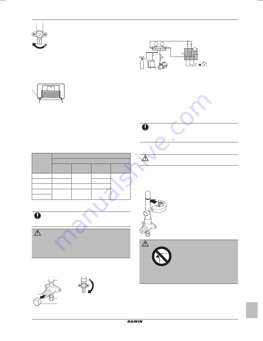
1

Remove the valve cover and make sure that the stop valves are
fully closed.


a

c

d

b


a

Service port and service port cover

b

Stop valve

c

Field piping connection

d

Stop valve cover

2

Connect the vacuuming/recovery unit through a manifold to the
service port of all stop valves.

p< p>

R410A

N2

b

c

e

a

f

g

h

d

A

C

(1)

D

B

a

Pressure reducing valve

b

Nitrogen

c

Weighing scales

d

Refrigerant R410A tank (siphon system)

e

Vacuum pump

f

Liquid line stop valve

g

Gas line stop valve

h

High pressure/low pressure gas line stop valve

A

Valve A

B

Valve B

C

Valve C

(1)

D

Valve D

(1)

Only for heat recovery mode.

NOTICE

Do  not  connect  the  vacuum  pump  to  the  suction  gas  stop
valve if the unit is intended to run in heat pump mode. This
will increase the risk of unit failure.

3

Recover  gas  and  oil  from  the  pinched  piping  by  using  a
recovery unit.

CAUTION

Do not vent gases into the atmosphere.

4

When  all  gas  and  oil  is  recovered  from  the  pinched  piping,
disconnect the charge hose and close the service ports.

5

Cut off the upper part of the liquid, gas, and high pressure/low
pressure  gas  stop  valve  pipes  along  the  black  line.  Use  an
appropriate tool (e.g. a pipe cutter, a pair of nippers).

WARNING

Never remove the pinched piping by brazing.

Any gas or oil remaining inside the stop valve may blow off
the pinched piping.

6

Make  sure  that  no  particles  remain  in  the  pipe.  Blow  out  any
particles with compressed air.

7

Wait  until  all  oil  is  dripped  out  before  continuing  with  the
connection  of  the  field  piping  in  case  the  recovery  was  not
complete.

Summary of Contents for RWEYQ10T9Y1B

Page 1: ...lation and operation manual VRV IV water cooled system air conditioner English Installation and operation manual VRV IV water cooled system air conditioner RWEYQ8T9Y1B RWEYQ10T9Y1B RWEYQ12T9Y1B RWEYQ1...

Page 2: ...8 19 20 21 22 23 24 25 Directivelor cu amendamentele respective Direktive z vsemi spremembami Direktiivid koos muudatustega Direktyvose su papildymais Direkt v s un to papildin jumos Smernice v platno...

Page 3: ...S vastaava kyll stysl mp tila M C Kylm aine N Varmuuspainelaitteen asetus P bar Valmistusnumero ja valmistusvuosi katso mallin nimikilpi Maxim ln p pustn tlak PS K bar Minim ln maxim ln p pustn teplot...

Page 4: ...19 5 7 Connecting the water piping 20 5 7 1 About connecting the water piping 20 5 7 2 To connect the water piping 20 5 7 3 To fill the water circuit 20 5 7 4 To insulate the water piping 20 5 8 Conn...

Page 5: ...ed installers end users Documentation set This document is part of a documentation set The complete set consists of General safety precautions Safety instructions that you must read before installing...

Page 6: ...it This installation manual concerns the VRV IV water cooled system air conditioner The unit is full inverter driven and can be used for cooling heat pump and heat recovery applications Model line up...

Page 7: ...er 4 Preparation 4 1 Preparing installation site 4 1 1 Installation site requirements of the outdoor unit Mind the spacing guidelines See the Technical data chapter CAUTION Appliance not accessible to...

Page 8: ...termine the proper size using the following tables and reference figure only for indication In case of heat pump mode A B B B C D F G E x y b a 3 1 2 4 5 1 2 VRV DX indoor unit 3 BP box 4 5 RA DX indo...

Page 9: ...meter size mm 18 22 15 9 19 1 24 26 34 19 1 22 2 36 42 F Piping between refrigerant branch kit and BP unit Heat pump mode in case of single outdoor unit Pipe size for direct connection on BP unit must...

Page 10: ...b a a To indoor unit b Piping between outdoor units NOTICE There are restrictions on the refrigerant pipe connection order between outdoor units during installation in case of a multiple outdoor unit...

Page 11: ...it MUST be handled in a different manner Install a water filter at the water inlet in order to prevent foreign materials such as dust sand from entering the plate heat exchanger Scale can stick to the...

Page 12: ...ow rate D Model D RWEYQ8 12 120 l min RWEYQ14 190 l min 3 Hydronic flow rate E The value E is the design flow rate calculated by the hydronic engineer when designing the building system Correct valve...

Page 13: ...ic component box cover Excessive force can deform the cover resulting in entering of water to cause equipment failure 4 SW8 2 1 5 2 Mounting the outdoor unit 5 2 1 To provide the installation structur...

Page 14: ...m of straight section can be ensured 120 mm 500 mm 5 3 4 To connect the refrigerant branching kit For installation of the refrigerant branching kit refer to the installation manual delivered with the...

Page 15: ...umstances Use the following procedure to remove the pinched piping 1 Remove the valve cover and make sure that the stop valves are fully closed a c d b a Service port and service port cover b Stop val...

Page 16: ...nt in the refrigerant piping for example water may have entered the piping first carry out the vacuum drying procedure below until all moisture has been removed All piping inside the unit has been fac...

Page 17: ...k the vacuum by pressurising with nitrogen gas to a gauge pressure of 0 05 MPa 0 5 bar and repeat steps 1 to 3 until all moisture has been removed 4 Depending on whether you want to immediately charge...

Page 18: ...CR 100 charge an additional 0 5 kg of refrigerant per outdoor unit In case of heat recovery mode Formula R X1 22 2 0 37 X2 19 1 0 26 X3 15 9 0 18 X4 12 7 0 12 X5 9 5 0 059 X6 6 4 0 022 1 04 A C R Addi...

Page 19: ...t the refrigerant tanks to each outdoor unit NOTICE The refrigerant charging port is connected to the piping inside the unit The unit s internal piping is already factory charged with refrigerant so b...

Page 20: ...he water circulation system otherwise the plate heat exchanger will freeze 4 Check if the water flow rate is correct otherwise the plate heat exchanger will freeze Measure any water pressure loss befo...

Page 21: ...oor unit PCB A1P b Unit A master outdoor unit c Unit B slave outdoor unit d Unit C slave outdoor unit e Outdoor unit other system transmission F1 F2 f Outdoor outdoor unit transmission Q1 Q2 g Indoor...

Page 22: ...f the 2 10 V DC output signal is 50 mW Exceeding this power can result in damage of the system Always use shielded cables with a minimal cross section of 0 75 mm and a length limited to 100 m The cont...

Page 23: ...refrigerant charge test run etc and making field settings demand operation low noise etc happens by way of operating the push buttons See also 6 1 2 Field setting components on page 23 6 1 3 To access...

Page 24: ...shed and normal the 7 segment display indication state will be as below default situation when shipped from factory Stage Display When turning on the power supply flashing as indicated First checks on...

Page 25: ...ws 1 5 The current Te target parameter position 1 6 The current Tc target parameter position 1 13 Shows the total number of connected outdoor units in case of multiple outdoor system 1 17 1 18 1 19 Sh...

Page 26: ...operation not only the outdoor unit but the connected indoor unit will operate as well Working on an indoor unit while performing a test operation is dangerous NOTICE Be sure to turn on the power 6 ho...

Page 27: ...lves opening Judgement of piping length In case Hydrobox units are present in the system the pipe length check and the refrigerant situation check will not be performed Make sure to carry out the syst...

Page 28: ...oor units 8 Troubleshooting 8 1 Solving problems based on error codes In case of a displayed malfunction code perform correcting actions as explained in the malfunction code table After correcting the...

Page 29: ...L 4D108945A A Charge port B Stop valve with service port 7 9 mm flare connection C Cooling water inlet D Cooling water outlet Charge port Service port Filter Check valve Pressure relief valve Solenoid...

Page 30: ...reless user interface m Water system connection Heat pump system g c g g h g g c c c d f e i j b a a Unit b Refrigerant piping c VRV DX indoor unit d LT Hydrobox unit e BP box required to connect Resi...

Page 31: ...over time restricting the energy transfer to the outdoor unit s coil Heating capability decreases and the system needs to go into defrost operation to be able to deliver enough heat to the indoor unit...

Page 32: ...s the air flow direction adjust button only for double flow multi flow corner ceiling suspended and wall mounted Refer to 12 4 Adjusting the air flow direction on page 32 for details To stop 5 Press t...

Page 33: ...nd in order to ensure the best possible maintenance of your units we recommend to enter into a maintenance and inspection contract on top of normal maintenance activities Our network of dealers has ac...

Page 34: ...r centralized control it shows that this is a slave user interface When the cool heat changeover remote control switch is installed and the display shows change over under centralized control this is...

Page 35: ...minutes 14 2 17 Symptom The inside of an outdoor unit is warm even when the unit has stopped This is because the crankcase heater is warming the compressor so that the compressor can start smoothly 14...

Page 36: ...4P452190 1A 2017 04 Copyright 2017 Daikin 4P452190 1 A 0000000Y...

Reviews: