background image

13 Piping installation

Installation and operation manual

16

FDA125A5VEB

Split system air conditioners

4P494410-1D – 2022.10

To check for water leaks

The  procedure  differs  depending  on  whether  electrical  wiring  is
already finished. When electrical wiring is not finished yet, you need
to  temporarily  connect  the  user  interface  and  power  supply  to  the
unit.

When installation of the system is not yet completed

1

Temporarily connect electrical wiring.

2

Remove the switch box cover (a).

3

Connect  the  single-phase  power  supply  (50  Hz,  230  V)  to
connections  No.  1  and  No.  2  on  the  terminal  block  for  power
supply and earth.

4

Reattach the switch box cover (a).

5

Turn ON the power.

6

Start  cooling  operation  (see 

"15.2  To  perform  a  test

run"

 [

4

 19]).

7

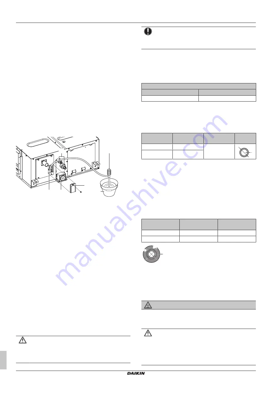
Gradually  pour  approximately  1  l  of  water  through  the  air
discharge outlet, and check for leaks.

c

e

b

d

a

f

a

Water inlet

b

Portable pump

c

Water inlet cover

d

Bucket (adding water through water inlet)

e

Drain outlet for maintenance

f

Refrigerant pipes

8

Turn OFF the power.

9

Disconnect the electrical wiring.

10

Remove the control box cover.

11

Disconnect the power supply and earth.

12

Reattach the control box cover.

When installation of the system is already completed

1

Start  cooling  operation  (see  the  reference  guide  or  the  service
manual of the user interface).

2

Gradually  pour  approximately  1  l  of  water  through  the  water
inlet, and check for leaks (see 

"When installation of the system

is not yet completed"

 [

4

 16]).

13

Piping installation

13.1

Preparing refrigerant piping

13.1.1

Refrigerant piping requirements

CAUTION

Piping MUST be installed according to instructions given in

"13  Piping  installation"

  [

4

  16].  Only  mechanical  joints  (e.g.

braze+flare connections) that are compliant with the latest
version of ISO14903 can be used.

NOTICE

The  piping  and  other  pressure-containing  parts  shall  be
suitable  for  refrigerant.  Use  phosphoric  acid  deoxidised
seamless copper for refrigerant piping.

▪ Foreign materials inside pipes (including oils for fabrication) must

be ≤30 mg/10 m.

Refrigerant piping diameter

For  piping  connections  of  the  indoor  unit,  use  the  following  piping
diameters:

Pipe outer diameter (mm)

Liquid pipe

Gas pipe

Ø9.5

Ø15.9

Refrigerant piping material

Piping material:

 phosphoric acid deoxidised seamless copper

Flare connections:

 Only use annealed material.

Piping temper grade and thickness:

Outer diameter

(Ø)

Temper grade

Thickness (t)

(a)

9.5 mm (3/8")

Annealed (O)

≥0.8 mm

t

Ø

15.9 mm (5/8")

Annealed (O)

(a)

Depending on the applicable legislation and the maximum
working pressure of the unit (see "PS High" on the unit name
plate), larger piping thickness might be required.

13.1.2

Refrigerant piping insulation

▪ Use polyethylene foam as insulation material:

▪ with a heat transfer rate between 0.041 and 0.052 W/mK (0.035

and 0.045 kcal/mh°C)

▪ with a heat resistance of at least 120°C

▪ Insulation thickness

Pipe outer diameter

p

)

Insulation inner

diameter (Ø

i

)

Insulation thickness

(t)

9.5 mm (3/8")

10~14 mm

≥13 mm

15.9 mm (5/8")

16~20 mm

≥13 mm

Ø

i

Ø

i

t

Ø

p

Ø

p

If  the  temperature  is  higher  than  30°C  and  the  humidity  is  higher
than RH 80%, the thickness of the insulation materials should be at
least  20  mm  to  prevent  condensation  on  the  surface  of  the
insulation.

13.2

Connecting the refrigerant piping

DANGER: RISK OF BURNING/SCALDING

13.2.1

To connect the refrigerant piping to the
indoor unit

CAUTION

Install  the  refrigerant  piping  or  components  in  a  position
where  they  are  unlikely  to  be  exposed  to  any  substance
which  may  corrode  components  containing  refrigerant,
unless  the  components  are  constructed  of  materials  that
are  inherently  resistant  to  corrosion  or  are  suitably
protected against corrosion.

Summary of Contents for FDA125A5VEB

Page 1: ...Installation and operation manual Split system air conditioners English Installation and operation manual Split system air conditioners FDA125A5VEB...

Page 2: ...j atbilst d m direkt v m vai regul m ja vien ie izstr d jumi tiek lietoti saska ar m su instrukcij m s v zhode s nasleduj cou imi smernicou ami alebo predpisom mi za predpokladu e sa v robky pou vaj v...

Page 3: ...s amended S I 2008 1597 Supply of Machinery Safety Regulations 2008 S I 2016 1101 Electrical Equipment Safety Regulations 2016 S I 2016 1091 Electromagnetic Compatibility Regulations 2016 following th...

Page 4: ...ical data 20 17 1 Wiring diagram 20 17 1 1 Unified wiring diagram legend 20 1 About the documentation 1 1 About this document WARNING Make sure installation servicing maintenance repair and applied ma...

Page 5: ...xternal static pressure for the unit Refer to the technical datasheet of your model for the setting range Make sure to install the canvas duct so vibrations are NOT transmitted to the duct or ceiling...

Page 6: ...and knowledge if they have been given supervision or instruction concerning use of the appliance in a safe way and understand the hazards involved Children SHALL NOT play with the appliance Cleaning...

Page 7: ...t is unhealthy to expose your body to the air flow for a long time CAUTION To avoid oxygen deficiency ventilate the room sufficiently if equipment with burner is used together with the system CAUTION...

Page 8: ...in this unit is mildly flammable Refer to the outdoor unit specifications for the type of refrigerant to be used WARNING The appliance using R32 refrigerant shall be stored so as to prevent mechanical...

Page 9: ...ce CAUTION NEVER touch the internal parts of the controller Do NOT remove the front panel Some parts inside are dangerous to touch and appliance problems may happen For checking and adjusting the inte...

Page 10: ...eration During defrost operation the indoor unit fan will stop operation and the following icon will appear on the home screen The system will resume normal operation after approximately 6 to 8 minute...

Page 11: ...efrigerant if applicable in this unit is mildly flammable Refer to the outdoor unit specifications for the type of refrigerant to be used WARNING The appliance using R32 refrigerant shall be stored so...

Page 12: ...igerant if applicable in this unit is mildly flammable Refer to the outdoor unit specifications for the type of refrigerant to be used 11 1 1 To remove the accessories from the indoor unit 16 8 1 1 3...

Page 13: ...nside of the unit 4 Reinstall the interchangeable plate When installing an air inlet duct select fixing screws that stick out 5 mm on the inside of the flange to protect the air filter from damage dur...

Page 14: ...ation insulation rubber to the hanging bolts When welding make sure NOT to spatter onto the drain pan or the air filter If the metal duct passes through a metal lath wire lath or metal plate of the wo...

Page 15: ...eld supply d Hanging bars field supply Combining drain pipes You can combine drain pipes Make sure to use drain pipes and T joints with the correct gauge for the operating capacity of the units 100 62...

Page 16: ...ompliant with the latest version of ISO14903 can be used NOTICE The piping and other pressure containing parts shall be suitable for refrigerant Use phosphoric acid deoxidised seamless copper for refr...

Page 17: ...at is regularly turned ON and OFF by the utility 14 1 Specifications of standard wiring components NOTICE We recommend using solid single core wires If stranded wires are used slightly twist the stran...

Page 18: ...at the interface point between the user s supply and the public system EN IEC 61000 3 12 European International Technical Standard setting the limits for harmonic currents produced by equipment conne...

Page 19: ...est run is only completed if there is no malfunction code displayed on the user interface See the service manual for the complete list of error codes and a detailed troubleshooting guideline for each...

Page 20: ...represented in the overview below by in the part code Symbol Meaning Symbol Meaning Circuit breaker Protective earth Connection Protective earth screw Connector A Rectifier Symbol Meaning Symbol Meani...

Page 21: ...stor R T Thermistor RC Receiver S C Limit switch S L Float switch S NG Refrigerant leak detector S NPH Pressure sensor high S NPL Pressure sensor low S PH HPS Pressure switch high S PL Pressure switch...

Page 22: ......

Page 23: ......

Page 24: ...4P494410 1D 2022 10 Copyright 2017 Daikin Verantwortung f r Energie und Umwelt...

Reviews: