13 Piping installation
Installation and operation manual
16
FDA125A5VEB
Split system air conditioners
4P494410-1D – 2022.10
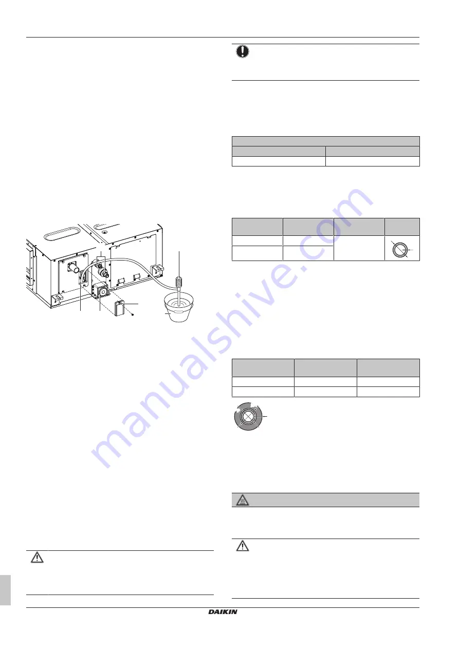
To check for water leaks
The procedure differs depending on whether electrical wiring is
already finished. When electrical wiring is not finished yet, you need
to temporarily connect the user interface and power supply to the
unit.
When installation of the system is not yet completed
1
Temporarily connect electrical wiring.
2
Remove the switch box cover (a).
3
Connect the single-phase power supply (50 Hz, 230 V) to
connections No. 1 and No. 2 on the terminal block for power
supply and earth.
4
Reattach the switch box cover (a).
5
Turn ON the power.
6
Start cooling operation (see
19]).
7
Gradually pour approximately 1 l of water through the air
discharge outlet, and check for leaks.
c
e
b
d
a
f
a
Water inlet
b
Portable pump
c
Water inlet cover
d
Bucket (adding water through water inlet)
e
Drain outlet for maintenance
f
Refrigerant pipes
8
Turn OFF the power.
9
Disconnect the electrical wiring.
10
Remove the control box cover.
11
Disconnect the power supply and earth.
12
Reattach the control box cover.
When installation of the system is already completed
1
Start cooling operation (see the reference guide or the service
manual of the user interface).
2
Gradually pour approximately 1 l of water through the water
inlet, and check for leaks (see
"When installation of the system
13
Piping installation
13.1
Preparing refrigerant piping
13.1.1
Refrigerant piping requirements
CAUTION
Piping MUST be installed according to instructions given in
16]. Only mechanical joints (e.g.
braze+flare connections) that are compliant with the latest
version of ISO14903 can be used.
NOTICE
The piping and other pressure-containing parts shall be
suitable for refrigerant. Use phosphoric acid deoxidised
seamless copper for refrigerant piping.
▪ Foreign materials inside pipes (including oils for fabrication) must
be ≤30 mg/10 m.
Refrigerant piping diameter
For piping connections of the indoor unit, use the following piping
diameters:
Pipe outer diameter (mm)
Liquid pipe
Gas pipe
Ø9.5
Ø15.9
Refrigerant piping material
▪
Piping material:
phosphoric acid deoxidised seamless copper
▪
Flare connections:
Only use annealed material.
▪
Piping temper grade and thickness:
Outer diameter
(Ø)
Temper grade
Thickness (t)
(a)
9.5 mm (3/8")
Annealed (O)
≥0.8 mm
t
Ø
15.9 mm (5/8")
Annealed (O)
(a)
Depending on the applicable legislation and the maximum
working pressure of the unit (see "PS High" on the unit name
plate), larger piping thickness might be required.
13.1.2
Refrigerant piping insulation
▪ Use polyethylene foam as insulation material:
▪ with a heat transfer rate between 0.041 and 0.052 W/mK (0.035
and 0.045 kcal/mh°C)
▪ with a heat resistance of at least 120°C
▪ Insulation thickness
Pipe outer diameter
(Ø
p
)
Insulation inner
diameter (Ø
i
)
Insulation thickness
(t)
9.5 mm (3/8")
10~14 mm
≥13 mm
15.9 mm (5/8")
16~20 mm
≥13 mm
Ø
i
Ø
i
t
Ø
p
Ø
p
If the temperature is higher than 30°C and the humidity is higher
than RH 80%, the thickness of the insulation materials should be at
least 20 mm to prevent condensation on the surface of the
insulation.
13.2
Connecting the refrigerant piping
DANGER: RISK OF BURNING/SCALDING
13.2.1
To connect the refrigerant piping to the
indoor unit
CAUTION
Install the refrigerant piping or components in a position
where they are unlikely to be exposed to any substance
which may corrode components containing refrigerant,
unless the components are constructed of materials that
are inherently resistant to corrosion or are suitably
protected against corrosion.
Summary of Contents for FDA125A5VEB
Page 22: ......
Page 23: ......
Page 24: ...4P494410 1D 2022 10 Copyright 2017 Daikin Verantwortung f r Energie und Umwelt...


